Manual
igus® smart plastics
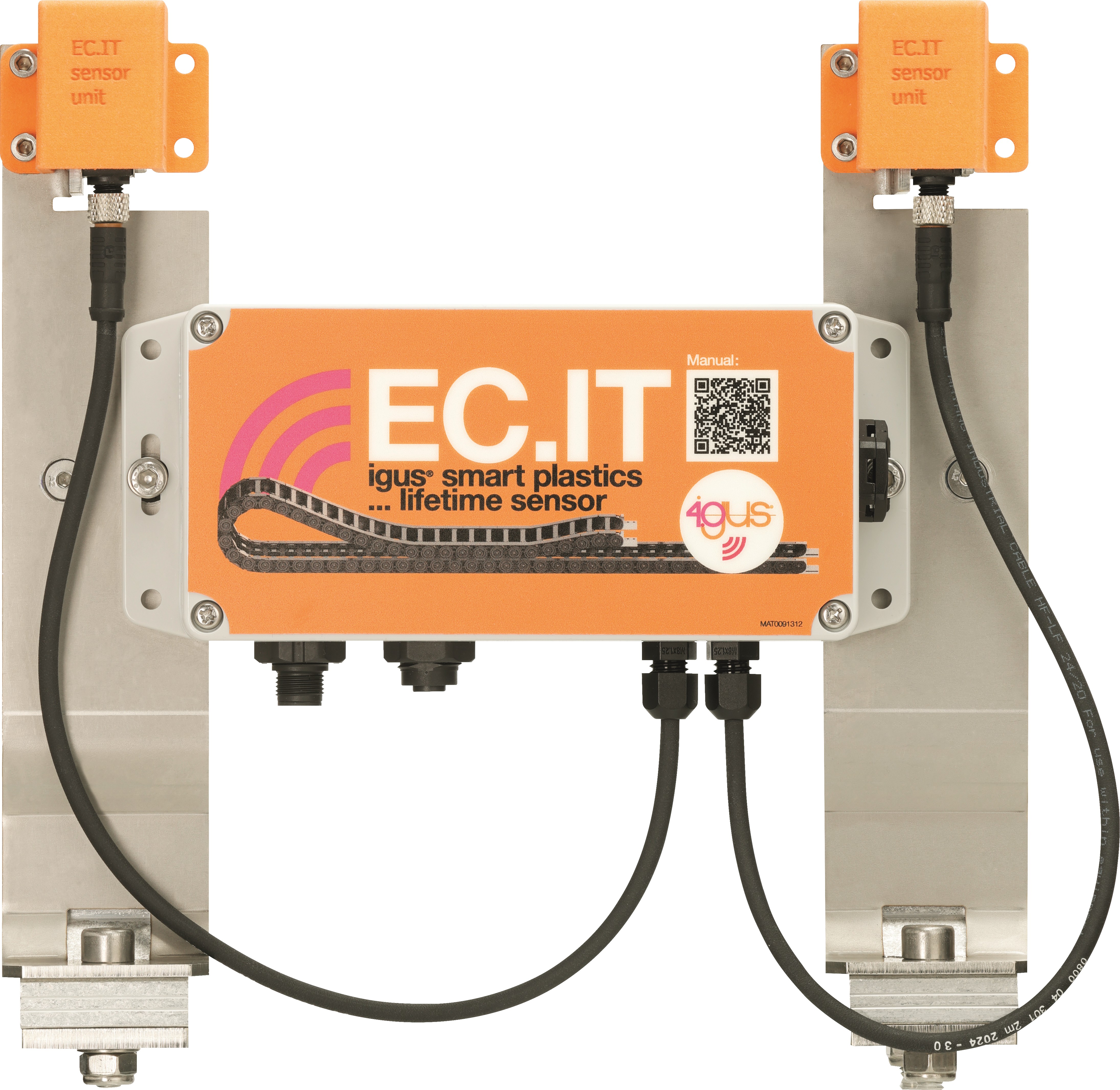
EC.IT
Sicherheit
Lesen Sie dieses Handbuch vor der Inbetriebnahme vollständig und beachten Sie alle Sicherheits- und Installationshinweise. Bei Integration in ein Gesamtsystem sind diese Informationen an den Endnutzer weiterzugeben.
Gewährleistung besteht nur gemäß den in diesem Handbuch genannten Spezifikationen und ist auf Reparatur oder Austausch des EC.IT beschränkt. Für Integrationsaufgaben, Folgeschäden, Fehlanwendung oder nicht autorisierte Änderungen übernimmt igus® keine Haftung; Änderungen am Produkt und an der Dokumentation bleiben vorbehalten.
Das EC.IT darf nur betrieben werden, wenn Sicherheits- und Installationshinweise eingehalten, das Gehäuse ESD-/EMV-konform montiert, das Gerät unverändert und einwandfrei ist und die in den technischen Daten angegebenen Betriebsgrenzen eingehalten werden.
Qualifiziertes Personal
Das EC.IT darf nur durch qualifiziertes Fachpersonal betrieben und gewartet werden.
-
Das Personal muss dieses Handbuch und ggf. existierende Zusatzdokumentationen gelesen und verstanden haben.
-
Das Personal muss mit allen relevanten geltenden Normen, Bestimmungen und Unfallverhütungsvorschriften vertraut sein.
-
Das Personal muss durch seine Ausbildung in der Lage sein, eventuelle Gefahren, die beim Gebrauch des Systems auftreten können, vorherzusehen bzw. zu erkennen.
-
Das Personal muss beim Einsatz der Sensoreinheit im Gesamtsystem die Sicherheit für Personen und Gegenstände sicherstellen können.
-
Das Personal muss bezüglich des Handlings von ESD empfindlichen Geräten geschult sein und alle nötigen Vorkehrungen treffen.
Die nachfolgenden Hinweistafeln werden im Handbuch einige Male erscheinen, sie sind klassifiziert, so dass Grad und Art einer Gefährdung markiert sind.
GEFAHR!
Sicherheitshinweise, die mit GEFAHR gekennzeichnet sind, weisen auf eine unmittelbare Gefahrensituation hin.
WARNUNG!
Sicherheitshinweise, die mit WARNUNG gekennzeichnet sind, weisen auf eine eventuelle Gefahrensituation hin. Eine Missachtung des Hinweises führt möglicherweise zu einem schweren oder gar tödlichen Unfall oder zu Sachschäden.
VORSICHT!
Sicherheitshinweise, die mit VORSICHT gekennzeichnet sind, weisen auf eventuelle Gefahrensituation hin. Eine Missachtung des Hinweises führt möglicherweise zu einem Unfall oder zu Sachschäden.
HINWEIS!
Sicherheitshinweise, die mit HINWEIS gekennzeichnet sind, weisen auf eine eventuelle Gefahrensituation hin. Eine Missachtung des Hinweises führt möglicherweise zu Sachschäden. Ebenfalls sind so allgemeine Hinweise und Erklärungen gekennzeichnet.
Produktübersicht
System variants
| Variant | Description |
|---|---|
| Without CF.P | - collecting lifetime information - data transfer to i.Cee:plus II or superwise Portal |
| With CF.P | - collecting lifetime information - CF.P (cable pull force monitoring) sensor connected - data transfer to i.Cee:plus II or superwise Portal |
Mechanical specifications
| Item | Value |
|---|---|
| D × W × H in millimeters incl. plugs & fasteners | Varies with trough system |
| Weight in grams | Approx. 1500 g |
| Fastening / assembly | At the guide trough, at ¼ travel distance |
| Colour | Grey |
Electrical specifications
Risk of destruction
An operating voltage above the voltage specified in the technical data destroys the EC.IT.SU.
Always select only the operating voltage specified in the technical data.
Power supply
| Item | Value |
|---|---|
| Power supply | 12–24 V DC (2A max.) |
| Protection | Reverse polarity Voltage transient protection included |
| Power supply potential-free contacts / I/O ports | 24 V DC (0.1A max.) dependent on operating voltage, open collector |
Load cell input
| Item | Value |
|---|---|
| Resolution | 24 bit |
| Analog gain | 128 |
| Sample rate | 10 or 80 samples per second |
| Excitation voltage | 3.0 V |
| Excitation voltage error | 0.05% |
| Excitation voltage temp drift | 12 ppm |
Digital input
| Item | Value |
|---|---|
| Activation voltage | 5 to 24 V |
| Current needed to activate | 6 mA |
Interfaces
| Item | Value |
|---|---|
| RS485 (baudrate) | 9600 baud |
| RS485 (output voltage) | 12 V |
| RS485 (max. current) | 100 mA |
| RS485 (protection) | ESD +15kV One unit load |
| LoRa wireless | 433 MHz |
| Mobile data | 2G LTE Cat NB LTE Cat M |
Electrical pinout
M12 power supply
| M12 pin | EC.IT function |
|---|---|
| 1 | GND |
| 2 | RS485 B - |
| 3 | Power in 24V DC |
| 4 | RS485 B + |
M12 loadcell connection
| M12 pin | EC.IT function |
|---|---|
| 1 | Signal + |
| 2 | Signal - |
| 3 | Excitation + |
| 4 | Excitation - |
| 5 | Sense + |
| 6 | Sense - |
| 7 | Shield |
Ambient conditions
Risk of malfunctions / fire / explosion / electric shock
Operate the EC.IT.SU neither in water nor in humid environments or in aggressive, flammable or explosive atmospheres and not in extreme vibrations.
Due to the self-heating of the device, it must be ensured that the outside temperature does not exceed 40°C.
If this is not guaranteed, a ventilated or air-conditioned housing must be used.
| Condition | Mode | Value |
|---|---|---|
| Temperature range | Operation | -20…40 °C |
| Storage | -40…45 °C | |
| Transport | -40…45 °C | |
| Relative humidity | Suitable for outdoor use, hermetically sealed otherwise non-condensing | |
| Protection | IP67 DIN EN 60529 |
Installation
VORSICHT!
Always lay the connecting cables of the device outside the traffic routes. There is a risk of tripping in the case of loosely laid cables.
Do not lay or squeeze cables over sharp edges, corners or moving parts. No objects may be hung or attached to cables.
Electrical equipment must be handled carefully. Movable cables and plugs must be protected against damage caused by trapping, shock and driving over with vehicles and equipment.
Electrical appliances, wires and plug-in devices may only be used if they meet the operational and local safety requirements with regard to operating mode and environmental influences.
Mechanical installation
The sensor unit should be installed at ¼ of the e-chains travel distance in direction to the e-chains radius. It is mounted at the guide trough.
Mounting (steel troughs)
- Fixed with screws of trough mounting angle
- Placed behind trough fold
Mounting (aluminium troughs)
- (Insert aluminium trough mounting steps/images here)
(Insert travel distance / d/4 sketch here if available.)
Electrical installation
WARNUNG!
Immediately switch the device voltage-free in the event of damage to the device or the connection cables and in the event of interference or unusual phenomena such as arcs, sparks, the smell of fire or noticeable noise.
Disconnect all electrical energy sources from the device. Do not try to repair the device yourself. Report defects immediately and contact the igus® branch responsible for your country.
Possible dangers: - Risk of electric shock - Danger of electric arcs - Injury risk - Risk of component destruction
Always turn off the power supply before disconnecting or establishing electrical connections in the system. Secure the power supply against reactivation.
Connected cables must not have exposed and stripped wire ends. Ensure that all connections are securely seated.
(Insert block diagrams / wiring figures for RS485 and LoRa here.)
Sensoren
Connection EC.IT.SU
Assignment of the extension cable / hardware connection
Available at igus® as:
| Article | Material no. |
|---|---|
| CFBUS.LB.022 | MAT904186720 |
Connection to i.Cee:plus II (RS485)
When connected to i.Cee:plus II over IS.ZB.I.23.02.0:
| Wire (color) | Designation / function |
|---|---|
| Brown | +24V DC |
| White | GND (power supply) |
| Yellow | A |
| Green | B |
| Shield | Shield |
Power supply
| Wire (color) | Name / function |
|---|---|
| Brown | +24V DC |
| White | GND |
NOTE
If battery runs empty it has to be recharged first and afterwards the system restarts operating as expected.
RS485 signal
| Wire (color) | Name / function |
|---|---|
| Yellow | A |
| Green | B |
LoRa connection
Wireless connection between EC.IT sensor and i.Cee:plus II. Power supply of EC.IT.SU is provided by extension cable.
Data transmission is done by LoRa communication protocol. Its limit depends on ambient conditions and can be up to 1 km.
The LoRa receiver IS.EC.IT.LORA.REC.02.BETA is mandatory to receive data with i.Cee:plus II.
Inbetriebnahme und Benutzeroberfläche
Commissioning and setup
With i.Cee:plus II by RS485
The sensor is connected via RS485 to an RS485/UART converter, which is directly connected to i.Cee:plus II.
With i.Cee:plus II by LoRa
The sensor has to be powered externally by 24 V DC. It sends its data via LoRa. A LoRa receiver receives messages nearby. The receiver is connected to i.Cee:plus II.
Setup at i.Cee:plus II user interface
Go to i.Cee configuration.
Without CF.P
NOTE
Only EC.IT without possibility of connecting CF.P will be displayed and set here.
- Select sensor (UID selectable when valid data is received)
- Switch to use the sensor for lifetime calculation (only one sensor can be used)
- Set chain / trough parameters
With CF.P
NOTE
Only EC.IT with possibility of connecting CF.P will be displayed and set here.
CF.P will be delivered pre-configured; changes can be done as described below.
- Select sensor (UID selectable when valid data is received)
- Switch to use the sensor for lifetime calculation (only one sensor can be used)
- Set e-chain® parameters
- Enable CF.P configuration (if available)
- Configure CF.P / set offset (if required)
- Reset error contact in EC.IT (if required)
EC.IT WiFi Portal (access)
- Open the housing at the 4 screws
- A WiFi network called At-… should appear; connect to it (UI starts directly)
- Push and hold the button until the LCD display shows WiFi ON
(Insert screenshots for portal overview, setup parameters, and firmware update procedure here.)
Problembehandlung
- Data transfer not available
-
Try sending
0to module. If it sends an answer the connection is working. -
WiFi portal does not open
-
Load/charge battery
-
Wrong calculation
-
Please set parameters
-
No power at the module?
- Check if battery is fully charged (4.1V DC)
- Check if power supply is connected
FAQS
- How do I retrieve lifetime information?
- i.Cee:plus II displays lifetimes in the user interface.
-
Superwise Portal shows an overview of all your e-chains at once in one user interface.
-
Is it possible to download the sensor's data from the user interface?
- No
Abkürzung
| Abbreviation | Description |
|---|---|
| EMC | Electromagnetic compatibility |
| ESD | Electrostatic discharge |
| GUI | Graphical User Interface |
| PLC | Programmable Logic Controller |
Regulatorik & Rechtliches
Einhaltung von EU‑Richtlinien Die CE‑Kennzeichnung auf dem EC.IT bestätigt die Konformität mit folgenden europäischen Richtlinien:
| Richtlinie | Beschreibung |
|---|---|
| 2014/30/EU Elektromagnetische Verträglichkeit (EMV) | Richtlinie des Europäischen Parlaments und des Rates zur Harmonisierung der Rechtsvorschriften der Mitgliedstaaten über die elektromagnetische Verträglichkeit |
| 2014/53/EU | Richtlinie des Europäischen Parlaments und des Rates zur Harmonisierung der Rechtsvorschriften der Mitgliedstaaten über die Bereitstellung von Funkanlagen auf dem Markt und zur Aufhebung der Richtlinie 1999/5/EG |
| 2011/65/EU RoHS | Richtlinie des Europäischen Parlaments und des Rates zur Beschränkung der Verwendung bestimmter gefährlicher Stoffe in Elektro‑ und Elektronikgeräten |
Die jeweils gültigen Richtlinien sind in der EU‑Konformitätserklärung des entsprechenden Geräts aufgeführt.
Hinweis zum Cyber Resilience Act (CRA) Das EC.IT enthält digitale Komponenten. Für solche Produkte gelten die Sicherheitsanforderungen des EU Cyber Resilience Act (Verordnung (EU) 2024/2847). Der CRA legt fest, dass Software und vernetzte Geräte über den gesamten Lebenszyklus sicher betrieben und aktuell gehalten werden müssen.
Damit Sie das EC.IT zuverlässig und sicher nutzen können, beachten Sie bitte:
- Installieren Sie bereitgestellte Firmware‑ und Softwareupdates regelmäßig.
- Verwenden Sie sichere Netzwerk- und Zugangseinstellungen.
- Ändern Sie Standardpasswörter sofort nach der Inbetriebnahme.
- Deaktivieren Sie nicht benötigte Schnittstellen oder Dienste.
Wenn Sie eine technische Auffälligkeit oder eine mögliche Sicherheitslücke feststellen, melden Sie diese bitte über den offiziellen igus‑Supportkanal oder über das Serviceportal. Der CRA verlangt außerdem, dass Anwender Zugang zu Informationen über Sicherheitsunterstützung, bekannte Risiken und Updateprozesse erhalten. Weitere Details finden Sie in den Dokumentationen dieses Produkts oder bei Ihrer nationalen Marktaufsichtsbehörde.
Hinweis zur EU‑Dual‑Use‑Verordnung (EU) 2021/821 Einzelne elektronische Komponenten und Sensoren in dem EC.IT können je nach technischer Ausführung unter die EU‑Dual‑Use‑Verordnung (EU) 2021/821 fallen. Diese Verordnung regelt Güter, die sowohl im zivilen als auch im militärischen Bereich eingesetzt werden können.
Für den Export in Länder außerhalb der EU kann daher eine Genehmigung erforderlich sein. Ob dies zutrifft, hängt vom Zielmarkt, der Anwendung und der jeweiligen technischen Konfiguration ab.
Bitte prüfen Sie vor einer Weitergabe oder Ausfuhr des Produkts:
- ob für Ihr Zielland Exportbeschränkungen bestehen,
- ob Ihre Anwendung als sicherheitskritisch oder militärisch gilt,
- ob eine Genehmigung nach geltenden Vorschriften notwendig ist.
Weitere Informationen finden Sie bei Ihrer nationalen Exportkontrollbehörde (z. B. BAFA in Deutschland) oder in den offiziellen EU‑Unterlagen.
Risk of injury due to interference of signals and devices
Disturbed signals can cause unforeseen device actions.
Perform wiring according to EMC guidelines. Failure to comply may result in death, serious injury or material damage.
EMC measures and effects
| Area | EMC measures | Effects |
|---|---|---|
| Device assembly | Use cable clamps or EMC cable glands for the shield pad; connect metallic parts over a large area | Good conductivity due to flat contact |
| Device assembly | Add switching devices such as contactors, relays or solenoid valves with interference suppression (diodes, varistors, RC links) | Reduce mutual interference coupling |
| Device assembly | Do not install electrical equipment and sensors near electromagnetic interference fields | Avoid malfunctions |
| Device assembly | Install electrical equipment in grounded metal control cabinet | Reduce interference and emission |
| Wiring | Keep cables as short as possible | Avoid capacitive and inductive interference couplings |
| Wiring | Do not lay sensor cables and signal lines together with cables for DC and AC voltage above 60 V in a cable duct | Avoid mutual interference coupling |
| Wiring | Ground shields of digital signal cables on both sides over a large area via EMC cable glands or conductive connector housings | Avoid interference, reduce emissions, avoid malfunctions |
| Wiring | Ground shields of analog sensor cables on one side over a large area via EMC cable glands or conductive connector housings | Avoid interference, reduce emissions, avoid malfunctions |
| Wiring | Connect shields of connected sensor and digital signal lines within a control cabinet to the terminals marked with (Shield) | Avoid interference, reduce emissions, avoid malfunctions |
Service
Customer service
de-smartplastics-service@igus.net
+49 (0) 2203 9649 9806
Technical support for igus® smart plastics
Documentation/FW
https://www.igus.eu/smart-maintenance/news/ec-it-sensor
Download manuals, FW updates and certificates
Website smart plastics
https://www.igus.eu/smart-maintenance
Contact
www.igus.eu
info@igus.de
+49 (0) 2203-9649-0
© 2026 igus® GmbH, Spicher Str. 1a, 51147 Cologne