Manual
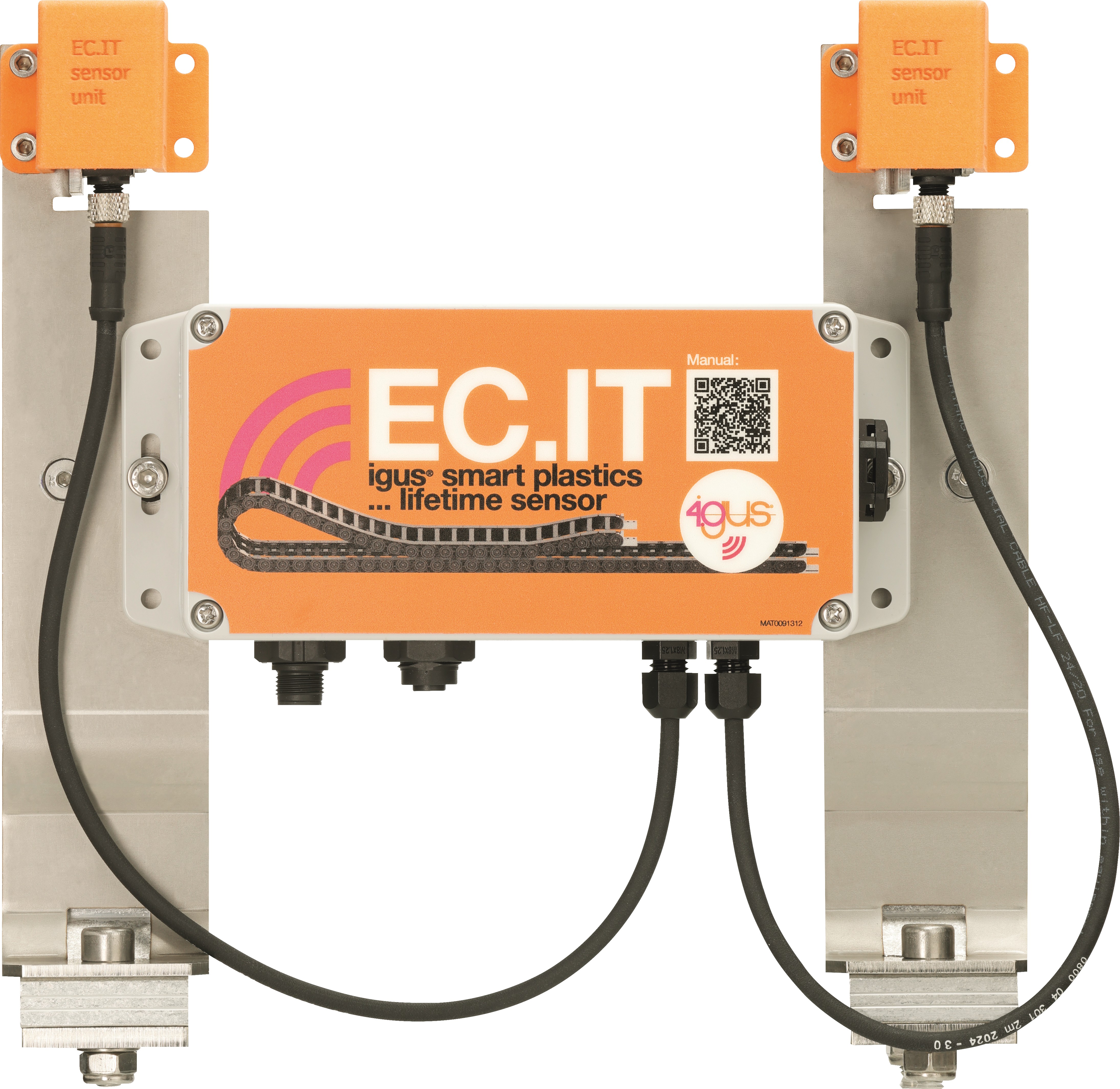
igus® smart plastics
EC.IT
Safety
Read this manual completely before commissioning and observe all safety and installation instructions. If integrated into an overall system, this information must be passed on to the end user.
Warranty applies only in accordance with the specifications stated in this manual and is limited to repair or replacement of the EC.IT. igus® accepts no liability for integration tasks, consequential damages, misuse, or unauthorized modifications; the right to make changes to the product and documentation is reserved.
The EC.IT may only be operated if the safety and installation instructions are observed, the housing is mounted in compliance with ESD/EMC requirements, the device is unmodified and in perfect condition, and the operating limits specified in the technical data are adhered to.
It seems like you didn't include any text to translate. Please provide the text you'd like me to translate into English.
Qualified Personnel
The EC.IT may only be operated and maintained by qualified specialist personnel.
-
Personnel must have read and understood this manual and any additional documentation that may exist.
-
Personnel must be familiar with all relevant applicable standards, regulations, and accident prevention regulations.
-
Personnel must be able, through their training, to anticipate or recognize any hazards that may arise during use of the system.
-
Personnel must be able to ensure the safety of persons and objects when using the sensor unit in the overall system.
-
Personnel must be trained in the handling of ESD-sensitive devices and must take all necessary precautions.
Please provide the text you'd like me to translate.
The following notice boards will appear several times in the manual. They are classified so that the degree and type of hazard are indicated.
DANGER!
Safety notices marked with DANGER indicate an immediate hazardous situation.
WARNING!
Safety notices marked with WARNING indicate a potential hazardous situation. Failure to observe the notice may result in a serious or even fatal accident or property damage.
CAUTION!
Safety notices marked with CAUTION indicate a potential hazardous situation. Failure to observe the notice may result in an accident or property damage.
NOTE!
Safety notices marked with NOTE indicate a potential hazardous situation. Failure to observe the notice may result in property damage. General notes and explanations are also marked in this way.
Product Overview
System variants
| Variant | Description |
|---|---|
| Without CF.P | - collecting lifetime information - data transfer to i.Cee:plus II or superwise Portal |
| With CF.P | - collecting lifetime information - CF.P (cable pull force monitoring) sensor connected - data transfer to i.Cee:plus II or superwise Portal |
Please provide the text you'd like me to translate.
Mechanical specifications
| Item | Value |
|---|---|
| D × W × H in millimeters incl. plugs & fasteners | Varies with trough system |
| Weight in grams | Approx. 1500 g |
| Fastening / assembly | At the guide trough, at ¼ travel distance |
| Colour | Grey |
Please provide the text you'd like me to translate.### Electrical specifications
Risk of destruction
An operating voltage above the voltage specified in the technical data destroys the EC.IT.SU.
Always select only the operating voltage specified in the technical data.
Power supply
| Item | Value |
|---|---|
| Power supply | 12–24 V DC (2A max.) |
| Protection | Reverse polarity Voltage transient protection included |
| Power supply potential-free contacts / I/O ports | 24 V DC (0.1A max.) dependent on operating voltage, open collector |
Load cell input
| Item | Value |
|---|---|
| Resolution | 24 bit |
| Analog gain | 128 |
| Sample rate | 10 or 80 samples per second |
| Excitation voltage | 3.0 V |
| Excitation voltage error | 0.05% |
| Excitation voltage temp drift | 12 ppm |
Digital input
| Item | Value |
|---|---|
| Activation voltage | 5 to 24 V |
| Current needed to activate | 6 mA |
Interfaces
| Item | Value |
|---|---|
| RS485 (baudrate) | 9600 baud |
| RS485 (output voltage) | 12 V |
| RS485 (max. current) | 100 mA |
| RS485 (protection) | ESD +15kV One unit load |
| LoRa wireless | 433 MHz |
| Mobile data | 2G LTE Cat NB LTE Cat M |
Electrical pinout
M12 power supply
| M12 pin | EC.IT function |
|---|---|
| 1 | GND |
| 2 | RS485 B - |
| 3 | Power in 24V DC |
| 4 | RS485 B + |
M12 loadcell connection
| M12 pin | EC.IT function |
|---|---|
| 1 | Signal + |
| 2 | Signal - |
| 3 | Excitation + |
| 4 | Excitation - |
| 5 | Sense + |
| 6 | Sense - |
| 7 | Shield |
| ### Ambient conditions |
Risk of malfunctions / fire / explosion / electric shock
Operate the EC.IT.SU neither in water nor in humid environments or in aggressive, flammable or explosive atmospheres and not in extreme vibrations.
Due to the self-heating of the device, it must be ensured that the outside temperature does not exceed 40°C.
If this is not guaranteed, a ventilated or air-conditioned housing must be used.
| Condition | Mode | Value |
|---|---|---|
| Temperature range | Operation | -20…40 °C |
| Storage | -40…45 °C | |
| Transport | -40…45 °C | |
| Relative humidity | Suitable for outdoor use, hermetically sealed otherwise non-condensing | |
| Protection | IP67 DIN EN 60529 |
Installation
CAUTION!
Always lay the connecting cables of the device outside the traffic routes. There is a risk of tripping in the case of loosely laid cables.
Do not lay or squeeze cables over sharp edges, corners or moving parts. No objects may be hung or attached to cables.
Electrical equipment must be handled carefully. Movable cables and plugs must be protected against damage caused by trapping, shock and driving over with vehicles and equipment.
Electrical appliances, wires and plug-in devices may only be used if they meet the operational and local safety requirements with regard to operating mode and environmental influences.
Please provide the text you'd like me to translate.
Mechanical installation
The sensor unit should be installed at ¼ of the e-chains travel distance in direction to the e-chains radius. It is mounted at the guide trough.
Mounting (steel troughs)
- Fixed with screws of trough mounting angle
- Placed behind trough fold
Mounting (aluminium troughs)
- (Insert aluminium trough mounting steps/images here)
(Insert travel distance / d/4 sketch here if available.)
Please provide the text you'd like me to translate.### Electrical installation
WARNING!
Immediately switch the device voltage-free in the event of damage to the device or the connection cables and in the event of interference or unusual phenomena such as arcs, sparks, the smell of fire or noticeable noise.
Disconnect all electrical energy sources from the device. Do not try to repair the device yourself. Report defects immediately and contact the igus® branch responsible for your country.
Possible dangers: - Risk of electric shock - Danger of electric arcs - Injury risk - Risk of component destruction
Always turn off the power supply before disconnecting or establishing electrical connections in the system. Secure the power supply against reactivation.
Connected cables must not have exposed and stripped wire ends. Ensure that all connections are securely seated.
(Insert block diagrams / wiring figures for RS485 and LoRa here.)## Sensors### Connection EC.IT.SU
Assignment of the extension cable / hardware connection
Available at igus® as:
| Article | Material no. |
|---|---|
| CFBUS.LB.022 | MAT904186720 |
Connection to i.Cee:plus II (RS485)
When connected to i.Cee:plus II over IS.ZB.I.23.02.0:
| Wire (color) | Designation / function |
|---|---|
| Brown | +24V DC |
| White | GND (power supply) |
| Yellow | A |
| Green | B |
| Shield | Shield |
Power supply
| Wire (color) | Name / function |
|---|---|
| Brown | +24V DC |
| White | GND |
NOTE
If battery runs empty it has to be recharged first and afterwards the system restarts operating as expected.
RS485 signal
| Wire (color) | Name / function |
|---|---|
| Yellow | A |
| Green | B |
LoRa connection
Wireless connection between EC.IT sensor and i.Cee:plus II. Power supply of EC.IT.SU is provided by extension cable.
Data transmission is done by LoRa communication protocol. Its limit depends on ambient conditions and can be up to 1 km.
The LoRa receiver IS.EC.IT.LORA.REC.02.BETA is mandatory to receive data with i.Cee:plus II.## Commissioning and User Interface### Commissioning and setup
With i.Cee:plus II by RS485
The sensor is connected via RS485 to an RS485/UART converter, which is directly connected to i.Cee:plus II.
With i.Cee:plus II by LoRa
The sensor has to be powered externally by 24 V DC. It sends its data via LoRa. A LoRa receiver receives messages nearby. The receiver is connected to i.Cee:plus II.
Setup at i.Cee:plus II user interface
Go to i.Cee configuration.
Without CF.P
NOTE
Only EC.IT without possibility of connecting CF.P will be displayed and set here.
- Select sensor (UID selectable when valid data is received)
- Switch to use the sensor for lifetime calculation (only one sensor can be used)
- Set chain / trough parameters
With CF.P
NOTE
Only EC.IT with possibility of connecting CF.P will be displayed and set here.
CF.P will be delivered pre-configured; changes can be done as described below.
- Select sensor (UID selectable when valid data is received)
- Switch to use the sensor for lifetime calculation (only one sensor can be used)
- Set e-chain® parameters
- Enable CF.P configuration (if available)
- Configure CF.P / set offset (if required)
- Reset error contact in EC.IT (if required)
EC.IT WiFi Portal (access)
- Open the housing at the 4 screws
- A WiFi network called At-… should appear; connect to it (UI starts directly)
- Push and hold the button until the LCD display shows WiFi ON
(Insert screenshots for portal overview, setup parameters, and firmware update procedure here.)## Troubleshooting
- Data transfer not available
- Try sending 0 to module. If it sends an answer the connection is working.
- WiFi portal does not open
-
Load/charge battery
-
Wrong calculation
-
Please set parameters
-
No power at the module?
- Check if battery is fully charged (4.1V DC)
- Check if power supply is connected
FAQS
- How do I retrieve lifetime information?
- i.Cee:plus II displays lifetimes in the user interface.
-
Superwise Portal shows an overview of all your e-chains at once in one user interface.
-
Is it possible to download the sensor's data from the user interface?
- No
Abbreviation
| Abbreviation | Description |
|---|---|
| EMC | Electromagnetic compatibility |
| ESD | Electrostatic discharge |
| GUI | Graphical User Interface |
| PLC | Programmable Logic Controller |
Regulatory & Legal
Compliance with EU Directives The CE marking on the EC.IT confirms conformity with the following European directives:
| Directive | Description |
|---|---|
| 2014/30/EU Electromagnetic Compatibility (EMC) | Directive of the European Parliament and of the Council on the harmonisation of the laws of the Member States relating to electromagnetic compatibility |
| 2014/53/EU | Directive of the European Parliament and of the Council on the harmonisation of the laws of the Member States relating to the making available on the market of radio equipment and repealing Directive 1999/5/EC |
| 2011/65/EU RoHS | Directive of the European Parliament and of the Council on the restriction of the use of certain hazardous substances in electrical and electronic equipment |
The applicable directives are listed in the EU declaration of conformity of the respective device.
Please provide the text you'd like me to translate.
Note on the Cyber Resilience Act (CRA) The EC.IT contains digital components. Such products are subject to the security requirements of the EU Cyber Resilience Act (Regulation (EU) 2024/2847). The CRA stipulates that software and networked devices must be operated securely and kept up to date throughout their entire lifecycle.
To ensure that you can use the EC.IT reliably and securely, please note the following: - Install provided firmware and software updates on a regular basis. - Use secure network and access settings. - Change default passwords immediately after commissioning. - Disable interfaces or services that are not required.
If you notice a technical anomaly or a potential security vulnerability, please report it via the official igus support channel or through the service portal. The CRA also requires that users have access to information about security support, known risks, and update processes. Further details can be found in the documentation for this product or from your national market surveillance authority.
Please provide the text you'd like me to translate.
Note on EU Dual-Use Regulation (EU) 2021/821 Individual electronic components and sensors in the EC.IT may, depending on their technical configuration, be subject to the EU Dual-Use Regulation (EU) 2021/821. This regulation governs goods that can be used in both civilian and military applications.
An export licence may therefore be required for export to countries outside the EU. Whether this applies depends on the destination market, the intended use, and the specific technical configuration.
Please verify the following before transferring or exporting the product: - whether export restrictions apply to your destination country, - whether your application is considered security-critical or military in nature, - whether authorisation is required under applicable regulations.
Further information is available from your national export control authority (e.g. BAFA in Germany) or in the official EU documentation.
Please provide the text you'd like me to translate.
Risk of injury due to interference of signals and devices
Disturbed signals can cause unforeseen device actions.
Perform wiring according to EMC guidelines. Failure to comply may result in death, serious injury or material damage.
EMC measures and effects
| Area | EMC measures | Effects |
|---|---|---|
| Device assembly | Use cable clamps or EMC cable glands for the shield pad; connect metallic parts over a large area | Good conductivity due to flat contact |
| Device assembly | Add switching devices such as contactors, relays or solenoid valves with interference suppression (diodes, varistors, RC links) | Reduce mutual interference coupling |
| Device assembly | Do not install electrical equipment and sensors near electromagnetic interference fields | Avoid malfunctions |
| Device assembly | Install electrical equipment in grounded metal control cabinet | Reduce interference and emission |
| Wiring | Keep cables as short as possible | Avoid capacitive and inductive interference couplings |
| Wiring | Do not lay sensor cables and signal lines together with cables for DC and AC voltage above 60 V in a cable duct | Avoid mutual interference coupling |
| Wiring | Ground shields of digital signal cables on both sides over a large area via EMC cable glands or conductive connector housings | Avoid interference, reduce emissions, avoid malfunctions |
| Wiring | Ground shields of analog sensor cables on one side over a large area via EMC cable glands or conductive connector housings | Avoid interference, reduce emissions, avoid malfunctions |
| Wiring | Connect shields of connected sensor and digital signal lines within a control cabinet to the terminals marked with (Shield) | Avoid interference, reduce emissions, avoid malfunctions |
Service
Customer service de-smartplastics-service@igus.net +49 (0) 2203 9649 9806
Technical support for igus® smart plastics
Documentation/FW https://www.igus.eu/smart-maintenance/news/ec-it-sensor Download manuals, FW updates and certificates
Website smart plastics https://www.igus.eu/smart-maintenance
Contact www.igus.eu info@igus.de +49 (0) 2203-9649-0
© 2026 igus® GmbH, Spicher Str. 1a, 51147 Cologne