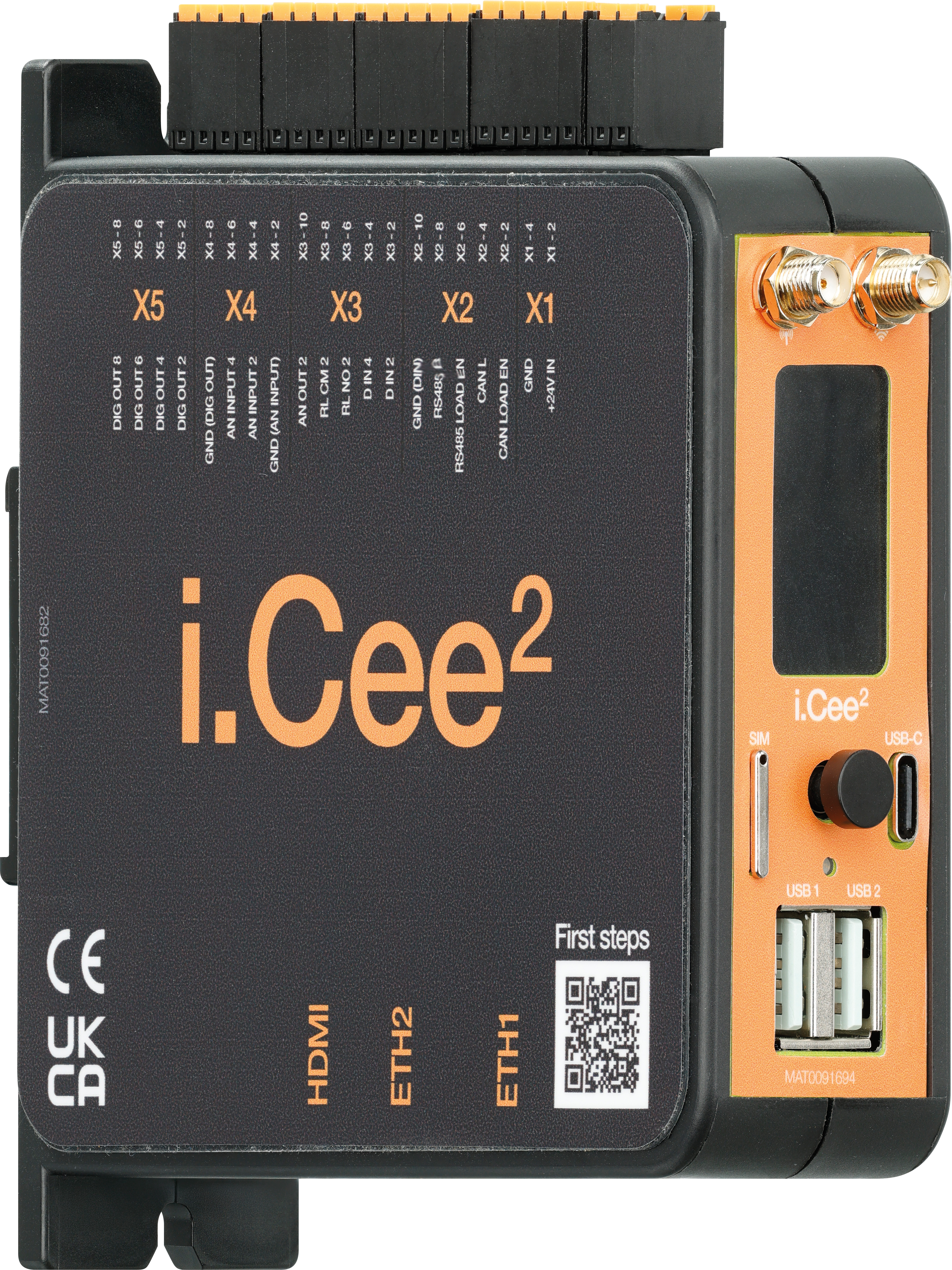
Lesen Sie dieses Handbuch vor der Inbetriebnahme vollständig. Beachten Sie alle Sicherheits- und Installationshinweise; produktspezifische Schutzmaßnahmen stehen in den jeweiligen Kapiteln. Bei Einsatz im Gesamtsystem sind diese Informationen an den Endnutzer weiterzugeben.
Gewährleistung besteht nur gemäß den in diesem Handbuch genannten Spezifikationen und beschränkt sich auf Reparatur bzw. Austausch des i.Cee². Für Integrationsaufgaben, Folgeschäden, Fehlanwendung oder nicht autorisierte Änderungen übernimmt igus® keine Haftung. Änderungen am Produkt und an der Dokumentation sind vorbehalten.
Das i.Cee² darf nur betrieben werden, wenn:
- Installation und Sicherheitshinweise eingehalten werden,
- das Gehäuse ESD-/EMV-konform montiert ist,
- keine Änderungen am Gerät vorgenommen wurden und ein einwandfreier Zustand vorliegt,
- die in den technischen Daten angegebenen Betriebsgrenzen eingehalten werden.
Qualifiziertes Personal
Das i.Cee² darf nur durch qualifiziertes Fachpersonal betrieben und gewartet werden.
Das Personal muss dieses Handbuch und ggf. existierende Zusatzdokumentationen gelesen und verstanden haben.
Das Personal muss mit allen relevanten geltenden Normen, Bestimmungen und Unfallverhütungsvorschriften vertraut sein.
Das Personal muss durch seine Ausbildung in der Lage sein, eventuelle Gefahren, die beim Gebrauch des Systems auftreten können, vorherzusehen bzw. zu erkennen.
Das Personal muss beim Einsatz der Sensoreinheit im Gesamtsystem die Sicherheit für Personen und Gegenstände sicherstellen können.
Das Personal muss bezüglich des Handlings von ESD empfindlichen Geräten geschult sein und alle nötigen Vorkehrungen treffen.
Die nachfolgenden Hinweistafeln werden im Handbuch einige Male erscheinen, sie sind klassifiziert, so dass Grad und Art einer Gefährdung markiert sind.
GEFAHR!
Sicherheitshinweise, die mit GEFAHR gekennzeichnet sind, weisen auf eine unmittelbare Gefahrensituation hin.
WARNUNG!
Sicherheitshinweise, die mit WARNUNG gekennzeichnet sind, weisen auf eine eventuelle Gefahrensituation hin. Eine Missachtung des Hinweises führt möglicherweise zu einem schweren oder gar tödlichen Unfall oder zu Sachschäden.
VORSICHT!
Sicherheitshinweise, die mit VORSICHT gekennzeichnet sind, weisen auf eventuelle Gefahrensituation hin. Eine Missachtung des Hinweises führt möglicherweise zu einem Unfall oder zu Sachschäden.
HINWEIS!
Sicherheitshinweise, die mit HINWEIS gekennzeichnet sind, weisen auf eine eventuelle Gefahrensituation hin. Eine Missachtung des Hinweises führt möglicherweise zu Sachschäden. Ebenfalls sind so allgemeine Hinweise und Erklärungen gekennzeichnet.
User App interface and functionalities exposed to the open part of the MQTT broker. Simplified interface to configure and obtain peripherals data. Connecting to the broker for this Area requires no credentials.
User App interface and functionalities exposed to the open part of the MQTT broker. Simplified interface to configure and obtain peripherals data. Connecting to the broker for this Area requires no credencials.
a) Set timer/alarm interruption
mode: Timer, alarm or none.
alarmSet: Date and time for alarm interruption (No effect if mode is timer or none).
timerSetSeconds: Period in seconds for timer interruption (No effect if mode is alarm or none).
tcState: State of the synchronization logic of the RTC, this value is non-persistent so every-time a reboot happens the value return to default (by default the value is ON)
User App interface and functionalities exposed to the open part of the MQTT broker.
This interface allows any external App to receive system-level metrics such as CPU load, RAM usage, disk usage, temperature, core frequency, system throttle status and uptime.
No credentials are required to subscribe to this topic.
The System Health Actor does not receive commands. It is fully autonomous and publishes its metrics every 1 second.
3.2 Peripherals version
The i.Cee² peripherals version is on topic systemHealth/versions
because it does not know how fast the eMMC is wearing.
i) Important Rule: Do Not Trust Short Observation Windows
During development, stress tests, boot corrections, actor restarts, or history synchronization, several wear levels may be registered in a very short time.
Although the math is correct, the result should not be trusted as a production RUL estimate.
The actor should avoid publishing a time-based RUL estimate when the observation period is too short.
Recommended rule:
Calculate time-based RUL only when:
- at least 2 real transitions exist;
- timestamps are strictly increasing;
- the total observation window is >= 7 days.
For production deployments, a stricter rule may be used:
Minimum observation window >= 30 days.
When the observation window is too short, publish:
This output avoids reporting a misleading value such as:
{"estimated_rul_days":0.41}
The correct interpretation is:
The eMMC is currently in WL03.
Estimated consumed lifetime is between 20% and 30%.
Estimated remaining lifetime is between 70% and 75%.
A reliable time-based RUL cannot yet be calculated.
m) Summary
The emmc_rul object provides two different types of information:
Type
Reliability
Description
Percentage-based RUL
Reliable immediately
Based directly on the current wear-level tier.
Time-based RUL
Requires history
Based on real wear-level transitions over time.
The SystemHealthActor should always expose the percentage-based RUL when a valid wear level exists.
The time-based RUL should only be exposed when the history is reliable enough to avoid misleading estimates.
3.5 Peripherals health
In order get the peripherals health we had to implement a SystemHealth actor in each bus manager (busi2c-0, busi2c-1, etc....).
{"life_time_estimation_a":{"field":{"register":"DEVICE_LIFE_TIME_EST_TYP_A","index":null,"description":"eMMC Life Time Estimation A","value":"0x01","value_int":1,"value_hex":"0x1"},"decoded":{"state":"normal","used_percent_min":0,"used_percent_max":10}},"life_time_estimation_b":{"field":{"register":"DEVICE_LIFE_TIME_EST_TYP_B","index":null,"description":"eMMC Life Time Estimation B","value":"0x01","value_int":1,"value_hex":"0x1"},"decoded":{"state":"normal","used_percent_min":0,"used_percent_max":10}},"pre_eol":{"field":{"register":"PRE_EOL_INFO","index":null,"description":"eMMC Pre EOL information","value":"0x01","value_int":1,"value_hex":"0x1"},"decoded":{"state":"normal"}}}
Fields
Field
Description
life_time_estimation_a
Wear estimation for eMMC memory type A.
life_time_estimation_b
Wear estimation for eMMC memory type B.
pre_eol
Pre-end-of-life state.
Lifetime Decoding
Raw Value
Decoded State
Meaning
0x00
not_defined
Not defined by device.
0x01
normal
0% to 10% estimated lifetime used.
0x02
normal
10% to 20% estimated lifetime used.
0x03
normal
20% to 30% estimated lifetime used.
0x04
normal
30% to 40% estimated lifetime used.
0x05
normal
40% to 50% estimated lifetime used.
0x06
normal
50% to 60% estimated lifetime used.
0x07
normal
60% to 70% estimated lifetime used.
0x08
normal
70% to 80% estimated lifetime used.
0x09
normal
80% to 90% estimated lifetime used.
0x0A
normal
90% to 100% estimated lifetime used.
0x0B
exceeded
Estimated maximum lifetime exceeded.
Pre-EOL Decoding
Raw Value
Decoded State
Meaning
0x00
not_defined
Not defined.
0x01
normal
Normal condition.
0x02
warning
Warning state. Monitor or plan replacement.
0x03
urgent
Urgent state. Replacement recommended.
emmc_extcsd.devices[].boot
{"partition_config":{"field":null,"decoded":null},"boot_config_protection":null,"boot_bus_conditions":null,"boot_write_protection":{"register":"BOOT_WP","index":null,"description":"Boot Area Write protection","value":"0x00","value_int":0,"value_hex":"0x0"},"boot_size":{"field":null,"decoded":null}}
Field
Type
Description
partition_config
object / null
Boot partition configuration, if available.
boot_config_protection
object / null
Boot configuration protection status.
boot_bus_conditions
object / null
Boot bus width/mode conditions.
boot_write_protection
object / null
Boot area write protection status.
boot_size
object / null
Boot partition size, if available.
emmc_extcsd.devices[].rpmb
RPMB means Replay Protected Memory Block. It is a protected eMMC area often used for secure storage.
Calculated user capacity, if sector count is available.
emmc_extcsd.devices[].partitioning
{"partitioning_support":{"register":"PARTITIONING_SUPPORT","index":null,"description":"Partitioning Support","value":"0x07","value_int":7,"value_hex":"0x7"},"partition_setting_completed":{"register":"PARTITION_SETTING_COMPLETED","index":null,"description":"Partitioning Setting","value":"0x00","value_int":0,"value_hex":"0x0"},"partition_attribute":{"register":"PARTITIONS_ATTRIBUTE","index":null,"description":"Partitions attribute","value":"0x00","value_int":0,"value_hex":"0x0"},"max_enhanced_area_size":{"register":"MAX_ENH_SIZE_MULT","index":null,"description":"Max Enhanced Area Size","value":"0x000747","value_int":1863,"value_hex":"0x747"},"enhanced_user_area_start":{"register":"ENH_START_ADDR","index":null,"description":"Enhanced User Data Start Address","value":"0x00000000","value_int":0,"value_hex":"0x0"},"enhanced_user_area_size":{"register":"ENH_SIZE_MULT","index":null,"description":"Enhanced User Data Area Size","value":"0x000000","value_int":0,"value_hex":"0x0"}}
Field
Type
Description
partitioning_support
object / null
Supported partitioning features.
partition_setting_completed
object / null
Indicates whether partition settings were finalized.
user_capacity
object / null
Partition attribute register.
max_enhanced_area_size
object / null
Maximum enhanced area size multiplier.
enhanced_user_area_start
object / null
Enhanced user data area start address.
enhanced_user_area_size
object / null
Enhanced user data area size.
4. TempSensor Actor
4.1 App Interfacing
User App interface and functionalities exposed to the open part of the MQTT broker. Simplified interface to configure and obtain peripherals data. Connecting to the broker for this Area requires no credencials.
User App interface and functionalities exposed to the open part of the MQTT broker. Simplified interface to control and interact with the TFT display, or frontal panel LCD screen. Connecting to the broker for this Area requires no credentials.
5.2 TFT Display Actor
The TFT Actor is responsible for:
Rendering static and informative screens on the TFT display
Reacting to joystick input (LEFT/ RIGHT/ CENTER/ UP/ DOWN)
Managing screen navigation and user confirmation flows
Providing feedback to the application via MQTT
a) Screen Carousel Concept
The TFT actor maintains an ordered list of screens (carousel).
Screens are navigated using the joystick:
- LEFT --> Previous screen
- RIGHT --> Next screen
The carousel wraps around:
- LEFT on first screen --> last screen
- RIGHT on last screen --> first screen
b) Screen Types
The TFT actor supports the following screen types:
Image Screen
Displays a static JPEG image
Default screen shown at boot
No user interaction required
Network Information Screen
Display a interface with information about the networks of the device
Updated on load
No user interaction required
c) Joystick Navigation Logic
Carousel Navigation:
Joystick Input
Action
LEFT
Previous screen
RIGHT
Next screen
DOWN
Refresh current screen
d) Boot Behavior
At system boot:
TFT actor initializes the display
Last available carousel is loaded
First screen is rendered
Joystick subscriptions are activated
Actor waits for runtime commands
e) Design Notes & Constraints
TFT actor does not expose joystick state
Joystick actor remains independent
TFT actor internally consumes joystick events
Carousel state is local to the TFT actor
Screen rendering is synchronous; input handling is asynchronous
Confirmation screens always require explicit CENTER press
5.3 User interaction through MQTT
Enabling interaction with the carousel using the topic tft/runtime/in . Actions available will be public to the user.
{"id":"TIMESTAMP","origin":"APP","task":{"action":"SET_CAROUSEL","params":{"startIndex":0,"screens":[{"type":"image","image":"default.jpg"},{"type":"image","image":"status.jpg"},{"type":"confirm","question":"Do you want to continue?"}]}}}
User App interface and functionalities exposed to the open part of the MQTT broker. Simplified interface to configure and obtain peripherals data. Connecting to the broker for this Area requires no credencials.
a) Configurations
Topic: analogInputs/config/in - Set ADC channels configurations
User App interface and functionalities exposed to the open part of the MQTT broker. Simplified interface to configure and obtain peripherals data. Connecting to the broker for this Area requires no credencials.
User App interface and functionalities exposed to the open part of the MQTT broker. Simplified interface to configure and obtain peripherals data. Connecting to the broker for this Area requires no credentials.
a) Set digital input pin/pins speed fast/slow
The fast speed setting supports edge detection speed up to 100 Hz and the slow speed settings supports up to 10 Hz.
Fast Mode generates a message on every I/O state change, which may result in a high message payload during operation. Fast Mode should therefore only be enabled when strictly required.
User App interface and functionalities exposed to the open part of the MQTT broker. Simplified interface to configure and obtain peripherals data. Connecting to the broker for this area requires no credencials.
User App interface and functionalities exposed to the open part of the MQTT broker. Simplified interface to configure and obtain peripherals data. Connecting to the broker for this Area requires no credencials.
The Buzzer Actor is responsible for controlling the onboard buzzer through MQTT commands. It receives runtime commands on an MQTT input topic, validates the requested buzzer operation, drives the buzzerthrough GPIO using libgpiod, and publishes status/final responses on an MQTT output topic.
The actor currently controls GPIO line 25 on /dev/gpiochip0, with ACTIVE_LOW = False. It creates a
GpiodBuzzerDriver instance and routes incoming MQTT actions to runtime handlers.
The supported runtime actions are:
Action
Description
BEEP
Plays a finite beep sequence, an infinite beep sequence, or a continuous tone
STOP
Stops the currently active buzzer playback
11.2 MQTT Topics
Topic
Direction
Description
buzzer/runtime/in
Input
Receives buzzer commands
buzzer/runtime/out
Output
Publishes status messages and final command responses
The actor subscribes to buzzer/runtime/in and publishes all status/final replies to buzzer/runtime/out.
11.3 Hardware and Datasheet Notes
The buzzer used is the MLT-8530 electro-magnetic SMD buzzer.
According to the datasheet:
Parameter
Value
Rated voltage
3.6 Vo-p
Operating voltage
2.5 ~ 4.5 Vo-p
Rated current
Max. 95 mA
Rated test frequency
2700 Hz
Duty cycle
50% square wave
Sound output
Min. 80 dB at 10 cm
Coil resistance
16 ± 3 Ω
Resonant frequency
2700 Hz
11.4 BEEP
The BEEP action supports two modes:
Mode
Description
sequence
Plays one or more beeps with gaps between them
continuous
Plays one continuous tone until STOP is received
If no mode is provided, the default mode is: sequence
All messages should be sent to the topic buzzer/runtime/in
The STOP command immediately forces the buzzer to OFF.
Buzzer State
After STOP, the buzzer is forced to OFF.
12. INA232 actor
12.1 Overview
The INA Actor is responsible for reading the i.Cee² INA232 power monitor and publishing the measuredelectrical values through MQTT.
The actor publishes:
Value
Unit
Description
voltage_v
V
Measured bus/input voltage
current_a
A
Measured current
power_w
W
Measured/calculated power
The INA232 is a current, voltage, and power monitor with an I²C/SMBus interface. It reports current, busvoltage, and power values through internal registers. The calibration register must be configured to obtainvalid current and power results.
12.2 Actor Behaviour
The INA Actor shall:
1. Start with a valid INA configuration.
2. Configure the INA232 device.
3. Read voltage, current and power once per second.
4. Publish the values to: ina/runtime/out
The actor does not need a request every second.
The publication is automatic and periodic.
12.3 Required Configuration
The actor requires a small configuration to correctly read and convert the INA232 measurements.
User App interface and functionalities exposed to the open part of the MQTT broker. Simplified interface to configure and obtainmodem (LTE) data. Connecting to the broker for this area requires no credentials.
13.2 Mobile (LTE Modem)
The Mobile actor manages the LTE modem using ModemManager (mmcli). It allows monitoring modem status, configuring connectivity (APN, operator,network mode), and performing diagnostics.
13.3 Scan Operators
Scans available network operators (requires SIM and modem enabled).
Unique request identifier. The same value isreturned in the response, allowing the applicationto match requests and responses.
origin
string
No
"APP"
Identifies who sent the request. Common values canbe
APP, NodeRED, CLI, or TestClient.
task
object
Yes
{...}
Main command object containing the CANopencommand alias and parameters.
task.alias
string
Yes
"CONFIG_CANOPEN"
Defines the command to execute. For this section,the alias must be
CONFIG_CANOPEN.
task.taskParams
object
Yes
{...}
Contains the configuration data to store inside theCANopen actor.
task.taskParams.defaults
object
No
{ "sdo_timeout":2.0 }
Defines default CANopen settings used by the actorwhen no command-specific value is provided.
task.taskParams.defaults.sdo_timeout
number
No
2.0
Default timeout, in seconds, used for SDOoperations. For example, 2.0
means the actor waitsup to 2 seconds for an SDO response.
task.taskParams.nodes
object
Yes
{ "motor_1": {...}}
List of logical CANopen nodes known by the actor.Each key is a user-defined node name.
task.taskParams.nodes.<NODE_NAME>
object
Yes
"motor_1"
Logical name used to reference a node later withoutrepeatedly sending its
node_id.
task.taskParams.nodes.<NODE_NAME>.node_id
integer
Yes
5
CANopen node ID on the CAN bus. Valid CANopennode IDs are normally in the range
1..127.
task.taskParams.nodes.<NODE_NAME>.steps_per_rev
integer
Recommended
4096
Number of raw position counts corresponding toone full mechanical revolution, 360°. The actor usesthis later to convert raw position into revolutions and angle_deg.
Response Parameters
Parameter
Type
Example
Description
id
string
"1777041089180"
Same request identifier received in the request. Used to correlate the
response with the original command.
origin
string
"canopen-actor"
Identifies the component that generated the response. For successful
handler replies, this is canopen-actor.
task
object
{...}
Main response object containing the executed alias and the command
result.
task.alias
string
"CONFIG_CANOPEN"
Alias of the command that was executed.
task.taskResult
object
{...}
Result object containing the configuration outcome.
task.taskResult.defaults.success
boolean
true
Indicates that the defaults configuration was successfully stored. This
field is present only if defaults was included in the request.
task.taskResult.<NODE_NAME>.success
boolean
true
Indicates that the logical node configuration was successfully stored.
Example: taskResult.motor_1.success = true.
task.taskResult.success
boolean
true
Generic success field. This appears when no specific defaults or nodes
result is generated.
task.taskResult.error
string
"unknown alias
CONFIG_X"
Error description. This field is present only when the command fails.
CONFIG_CANOPEN does not communicate with the CANopen device directly. It stores logical node configuration inside the actor so that later runtime
commands can refer to nodes by name instead of always sending the numeric node_id.
Configure one CANopen Transmit PDO
Configures a TPDO to transmit position data.
The handler validates pdo_num as 1..4, defaults map_index to 0x6004, map_subindex to 0x00, map_bits to 32, transmission_type to 255 , event_timer_ms
- Keeps strict separation between transport and semantics.
15 SMS Actor
15.1 Overview
The i.Cee² system can be remotely controlled over SMS. The SMS Actor listens to the cellular modem for incoming text messages and reacts to them in two ways: it reports every received SMS over MQTT, and it recognises a small set of predefined text commands that trigger actions directly on the device — without needing network or MQTT connectivity.
This is useful when a device is unreachable over its normal network path (e.g. no internet, VPN down, misconfigured mobile connection) but still has GSM/SIM coverage. An operator can send a plain SMS to the device's SIM number to remotely reboot it, reset its mobile connection, toggle its digital outputs/relays, or manage SSH/mobile data/VPN.
The SMS Actor does not expose a request/response MQTT command interface for external callers, like other actors (e.g. the eMMC actor). It is event-driven: it reacts to SMS messages arriving on the modem and publishes results to MQTT. There is no .../runtime/intopic for external callers to send it commands over MQTT. Internally, the actor does use an MQTT request/response bridge to the Digital Outputs and Relays actors to carry out the OUT##/RL# commands (see Command execution).
15.2 Supported SMS Commands
The actor recognises two kinds of commands:
Fixed commands — the trimmed SMS body must exactly equal one of the values below. The auto-reply (if any) is fixed and is sent before the action executes, since the action itself may interrupt connectivity.
Parameterized commands — the SMS body matches a pattern with a parameter (output index, on/off, open/close). The auto-reply reflects the actual result of the action and is sent after it executes.
A single SMS may contain multiple lines, but every recognised line must be the same action — e.g. several RL#:Open|Close lines to drive both relays together. Mixing different actions in one SMS (even two different parameterized commands, or a parameterized command together with a fixed one) is rejected outright: nothing executes. See Multiple commands per SMS.
a) Fixed commands
SMS text
Action
Auto-reply SMS
Destructive
reboot
Reboots the device
none
Yes
resetMobileConnection
Resets the mobile connection (modem disable/enable cycle)
resetOnGoing
Yes
b) Parameterized commands
SMS text
Action
Auto-reply SMS (sent after execution)
Destructive
OUT[##]:High|Low
set_digital_output
OUT[##]St:High|Low
No
RL[1|2]:Open|Close
set_relay
RL[1|2]St:Open|Close
No
VPN:On|Off
set_vpn
VPNST:On<IpAddress>|VPNST:Off
No
SSH:On|Off
set_ssh
SSHST:On|Off
No
MobileData:On|Off
set_mobile_data
MobileDataStatus:On|Off
Yes (interrupts mobile connectivity)
## is a zero-padded digital output index 01-08, mapped to DO1-DO8. Any other index (e.g. OUT09, OUT99) is treated as an unrecognised SMS.
RL1/RL2 map to the same DO1/DO2 hardware naming used internally by the relay actor.
Matching is case-sensitive and exact — the SMS body must equal/match one of the patterns above (after trimming whitespace).
Any SMS that does not match a known fixed or parameterized command is still reported over MQTT (SMS_RECEIVED) but no action is taken.
An SMS whose recognised lines are not all the same action (e.g. a relay command mixed with reboot, or with a digital output command) is treated the same way: reported via SMS_RECEIVED, but no command runs and no auto-reply is sent (see Multiple commands per SMS).
Unlike the fixed commands, a parameterized command's auto-reply is only sent when the action succeeds. If it fails, no SMS reply is sent, but the failure is still published over MQTT (see Command result (parameterized commands)).
Security note: there is currently no sender allow-list or authentication on inbound SMS commands. Any SMS with the exact matching text/pattern will trigger the corresponding action, regardless of sender. Restrict knowledge of the SIM number and treat it as a sensitive credential.
c) Multiple commands per SMS
An SMS body can carry several commands at once, one per line, so a single message can drive multiple outputs/relays together, e.g.:
RL1:Close
RL2:Close
This is accepted because both lines are the same action (set_relay). But every recognised line in the SMS must be the same action — mixing, e.g.:
RL1:Close
reboot
is rejected outright: none of the lines run, only a warning is logged, and no auto-reply is sent (same as an SMS matching no command at all). This applies to any combination of different actions, not just fixed-vs-parameterized — a set_relay line mixed with a set_digital_output line is rejected too.
Each non-blank line is matched independently against the known command patterns (fixed and parameterized alike). Lines that don't match anything are silently skipped and don't count toward the action check — only the recognised lines' actions are compared.
If every recognised line shares the same action, commands run sequentially, in the order their lines appear in the SMS. If the same output/relay appears more than once (e.g. RL1:Close then RL1:Open), the last one wins.
Each line is tracked as its own SMS_COMMAND_STARTED / command-result MQTT event (see MQTT Interface), with smsPayload set to that line's text rather than the full SMS body.
The auto-replies for all lines that succeeded are combined into a single SMS reply, one line per successful command, in the same order the commands were received (e.g. RL1St:Close\nRL2St:Close). Lines whose action failed contribute no reply line, mirroring the single-command behaviour.
15.3 How It Works
a) Startup cleanup
When the actor starts, it deletes all pre-existing SMS stored on the modem/SIM. This is a one-shot cleanup, not a periodic action, and can be disabled via configuration.
b) Listening for SMS
The actor runs a background thread subscribed to ModemManager D-Bus signals (Added and Completed on the Modem.Messaging interface). There is no polling loop — processing is purely event-driven, triggered as soon as the modem reports a new SMS object.
Because multipart SMS may not be immediately readable, the actor retries reading a new message a few times before giving up (10 attempts, 0.75s apart). If the message still cannot be read, it is logged as a warning and deleted without being reported.
c) Message deletion
Processed SMS are deleted from the modem/SIM after handling, by default. This keeps SIM storage from filling up and prevents the same message from being processed twice.
d) Command execution
Fixed commands: once matched, the fixed auto-reply (if any) is sent, then the actor waits briefly (2s) to let the MQTT publish and SMS reply/delete complete, then executes the underlying action:
Parameterized commands: the SMS is deleted immediately (same as fixed commands), the action executes, and only then — if it succeeded — is the computed auto-reply sent:
set_digital_output (OUT##:High|Low) — calls the Digital Outputs actor (busi2c-3 process) over an MQTT request/response bridge: publishes {"action": "SET", "taskParams": {"DO<n>": {"state": "high"|"low"}}} to digitalOutputs/runtime/in and awaits the matching response on digitalOutputs/runtime/out (correlated by id, 5s timeout).
set_relay (RL1|2:Open|Close) — same bridge mechanism, targeting the Relays actor (busi2c-1 process) via relayOutputs/runtime/in/relayOutputs/runtime/out.
set_ssh (SSH:On|Off) — runs systemctl start|stop on both ssh.socket and ssh.service (start/stop only, does not change boot-time enablement). Both units are stopped/started — ssh.socket alone stays listening on :22 and socket-activates ssh.service on the next connection, so stopping only the service would not actually block new SSH sessions.
set_mobile_data (MobileData:On|Off) — reuses the same nmcli/systemd modem enable/disable flow as the MQTT SET_MODEM_STATE command (not the mmcli-based path used by resetMobileConnection), so there is a single mechanism for enabling/disabling the modem connection.
set_vpn (VPN:On|Off) — runs systemctl start|stop on wg-quick@wg0.service (the WireGuard tunnel, already provisioned with keys/peer/AllowedIPs on both the device and the gateway — this command only starts/stops it, it never touches the config). On On, the reply includes the tunnel's IPv4 address read back via ip -4 addr show dev wg0 (e.g. VPNST:On10.100.0.28); if the address can't be read, the reply is still VPNST:On with no address. On Off, the reply is VPNST:Off.
15.4 MQTT Interface
The SMS Actor only publishes — it does not subscribe to any inbound command topic.
Publish topic:sms/runtime/out (QoS 0, not retained)
All messages follow the standard i.Cee² MQTT envelope, with the result carried in task.taskResult (not task.taskParams, unlike the request/response actors):
Auto-reply text sent back to the sender. null/absent if none is defined.
destructive
boolean
true if the command changes device state (both current commands are).
c) Command result
Published once the command's action has finished executing. The task.action field is the internal command identifier (e.g. "reboot", "reset_mobile_connection"), not a fixed name.
Published as soon as an incoming SMS matches a parameterized command — before the action executes and before the auto-reply is known. answer is always null here; the actual reply is only computed after execution (see below).
If the SMS carries multiple commands (one per line, see Multiple commands per SMS), this event is published once per matched line, and smsPayload is that line's text, not the full SMS body.
Published once the command's action has finished. task.action is the internal command name (set_digital_output, set_relay, set_ssh, set_mobile_data, set_vpn). taskResult.answer is the SMS reply that was actually sent — null/absent if the action failed or is not implemented.
For a multi-line SMS, this event is published once per matched line, each with its own smsPayload (that line's text) and result. However, taskResult.answer here is that line's own reply text (e.g. "RL1St:Close"); the SMS actually sent to the user is the combination of every successful line's answer (see Multiple commands per SMS).
true if the action fully succeeded. When false, no SMS auto-reply was sent.
from
string
Sender's phone number.
smsPayload
string
Original SMS text that triggered the command.
answer
string | null
SMS reply text actually sent, or null if none was sent (failure).
result
object
Handler-specific outcome. Always has success; set_digital_output/set_relay also carry the bridged actor's response (output/relay, state); set_ssh/set_vpn carry returnCode/stdout/stderr; set_vpn also carries tunnelIp (the wg0 IPv4 address, null if On succeeded but the address couldn't be read back).
15.6 Interpreting the Results
a) success: false on SMS_RECEIVED
The modem reported a new SMS object, but its content could not be read after repeated retries (typically a multipart message that never completed assembly). The message is deleted and no further processing occurs.
b) destructive: true
Both currently supported commands (reboot, reset_mobile_connection) change device state. There is no non-destructive command in the current table.
c) result.error: "no_modem_found"
The modem could not be located over D-Bus at the time the action ran. This can happen if the modem was disconnected or ModemManager restarted between the SMS being received and the action executing.
d) No response to unrecognised SMS
If an incoming SMS does not match any entry in the command table (fixed or parameterized), it is reported via SMS_RECEIVED only. No auto-reply is sent, and no action is executed.
e) Mixed commands in one SMS are rejected
If an incoming SMS's recognised lines are not all the same action (e.g. a relay command mixed with reboot, or with a digital output command), the whole message is rejected: a warning is logged server-side and the SMS is reported via SMS_RECEIVED, but no command runs and no auto-reply is sent — same as an SMS matching no command at all. Sending multiple lines of the same action (e.g. several RL# lines) is still fully supported.
f) Digital output / relay bridge timeout
set_digital_output and set_relay call the Digital Outputs / Relays actors over MQTT and wait up to 5s for a response. If that actor process is down or doesn't answer in time, the request raises a timeout, success is false in the command result, and no auto-reply is sent.
g) VPN systemd unit
set_vpn runs systemctl start|stop on wg-quick@wg0.service, confirmed on-device via systemctl status wg-quick@wg0. This is the WireGuard tunnel used to reach the device from the gateway; its config (keys, peer, AllowedIPs) is provisioned out-of-band on both ends and is never touched by this command — it only starts/stops the already-configured tunnel. wg-quick@wg0.service is a oneshot unit with RemainAfterExit=yes, so systemctl start only returns once wg-quick has finished assigning the interface address, which is why no extra wait/poll is needed before reading back the IP for the On reply. There is a separate, unrelated read-only systemctl is-active openvpn check elsewhere in the codebase (used only for a status display, not for control) — it targets a different, apparently unused OpenVPN unit and has no bearing on this command.
h) SSH systemd units
set_ssh runs systemctl start|stop on both ssh.socket and ssh.service, confirmed on-device via systemctl list-units | grep -i ssh. On this image, ssh.service is TriggeredBy: ssh.socket and both are enabled independently — stopping only ssh.service leaves ssh.socket listening on :22, and it socket-activates a fresh sshd on the next connection attempt, so SSH would stay reachable despite SSH:Off reporting success. Some distros name the service unit sshd instead; reconfirm both unit names if targeting a different image.
15.7 Boot Behaviour
On every boot, the actor:
Connects to MQTT and starts a background reconnector (exponential backoff, 1s → 30s cap, if the connection drops).
Deletes all pre-existing SMS on the modem/SIM (unless disabled via configuration).
Starts the D-Bus listener thread and begins reacting to incoming SMS.
15.8 There is no periodic check — all processing after boot is triggered by modem D-Bus signals.
15.9 Notes
The SMS Actor keeps no persistent state across restarts (no EEPROM, file, or database). In-memory bookkeeping only tracks SMS already seen/being processed, to avoid double-handling from overlapping D-Bus signals.
Message deletion after processing is enabled by default; this can be disabled via configuration if a full SMS audit trail is needed on the modem/SIM itself (subject to SIM storage limits).
There is currently no sender allow-list or authentication on inbound SMS commands — any device holding the SIM number can trigger any of the commands above by sending the matching text.
set_digital_output/set_relay are the only commands that depend on another actor process (busi2c-3/busi2c-1) being up and reachable over MQTT; all other commands run entirely within the SMS actor's own process.
These easy-to-deploy flows aim to make the integration of the i.Cee² into any scenario faster by adding anabstraction layer between the user and the stack. This is achieved through the use of subflows, which containthe code needed for the features and where changes can be made if necessary, exposing a node that "hides"that more complex integration.
1. Import Flows to Example Folder
To import the flows and add them to the Node-RED examples folder, execute the following:
1.1 First copy the i.Cee² folder to a folder with permissions, i.e. /pi
1.2 Copy the folder to the Node-RED examples folder using the command:
This flow implements a demonstration of acquisition and control of analog ports AI1..AI4 via MQTT and theNode-RED Dashboard 2.0. The system is divided into two main subflows: Analog Inputs, for readingchannels AI1 to AI4, and Analog Outputs, for configuring/reading channels AO1 and AO2. The main logic isencapsulated in subflows, allowing reuse in other tabs or projects.
2. Main Components
Component
Function
Analog Inputs
Subflow responsible for requesting AI1..AI4 readings, receiving results, and forwarding values to gauges/UI and live topic.
Analog Outputs
Subflow responsible for sending AO1/AO2 currents, synchronising sliders/gauges, and reading the current state of outputs.
Analog Demo
Main tab that instantiates both subflows and displays the Dashboard widgets.
MQTT broker i.Cee²
Local broker at 127.0.0.1:1883
Dashboard 2.0
Analog Demo ports page
3. Subflow Analog Inputs
3.1 Function
The Analog Inputs subflow allows selecting which AI channels should be read and in which unit/type eachchannel should operate: voltage (voltage) or current (current). The subflow has four outputs, one perchannel: AI1, AI2, AI3 and AI4.
If no channel is active, the function emits the warning "No AI channels selected" and does not send a message.
3.4 Configuring the AI mode
The group Set acquisition mode allows sending the configuration of the analogue channels to analogInputs/config/in. The function Set AIX mode creates taskParams only for the active channels and sets each channel as:
{"mode":"single","type":"voltage"}
It also saves the configuration in flow context via flow.set("AI_config", taskParams). If the configured type is neither voltage nor current, the function uses voltage as a fallback and emits a warning.
4. Subflow Analog Outputs
4.1 Function
The subflow Analog Outputs controls and monitors two analogue current outputs: AO1 and AO2. It has one input, used by the Dashboard sliders, and two outputs, one for AO1 and another for AO2.
4.2 ENV Variables
Variable
Type
Default value
Description
AO1_enabled
bool
true
Enables/disables output AO1.
AO1_current
num
5.5
Initial/default current of AO1 in mA.
AO2_enabled
bool
true
Enables/disables output AO2.
AO2_current
num
5.5
Initial/default current of AO2 in mA.
The function set current output receives messages from the sliders with values between 0 and 20 mA. Invalid values are rejected with a warning in the debug panel.
The response is received on analogOutputs/runtime/out. The parser extracts AO1.current and AO2.current and prepares a payload in the appropriate format for writing to a database or further processing:
[{"ao1":5.5,"ao2":5.5}]
5. Operating flow
5.1 Reading analogue inputs
The inject on the subflow Analog Inputs triggers the function acquire AIx channels.
The function checks which channels are active in the ENV variables.
A request is published on analogInputs/runtime/in.
The hardware/service responds on analogInputs/runtime/out.
The parser separates the values by channel and updates the AI gauges.
5.2 Configuring analogue outputs
The user moves the AO1 or AO2 slider.
The subflow Analog Outputs receives the value with msg.topic equal to the channel.
The function validates whether the current is between 0 and 20 mA.
The value is stored in flow context.
The configuration is published on analogOutputs/config/in.
The slider, gauge and text of the changed channel are synchronised.
5.3 Reading analogue outputs
A periodic inject sends a READ request for AO1 and AO2 on analogOutputs/runtime/in.
The system responds on analogOutputs/runtime/out.
The parser converts the values into a structured payload with fields ao1, ao2 and tag source_tag.
6. Validations and protections implemented
Area
Validation
Behaviour on error
AI selection
At least one active AI channel
Returns null and warning "No AI channels selected".
AI type
Only voltage or current
Falls back to voltage.
AO current
Finite number between 0 and 20 mA
Returns null and warning "Invalid current".
AO enable
Checks AO1_enabled / AO2_enabled
Disabled channel sends current 0.
7. Requirements
Node-RED with subflow support.
@flowfuse/node-red-dashboard version 1.30.2.
MQTT broker.
External service/hardware that stimulates/responds to the analogInputs/* and analogOutputs/* topics.
Digital Demo
8. Objective
This flow demonstrates the control and monitoring of digital ports through
Node-RED, MQTT and Dashboard 2.0.
It is composed of two main subflows:
Component
Function
Digital Inputs
Reads the states of DI1..DI4 and sends them to LEDs on the Dashboard.
Digital Outputs
Controls DO1..DO4 through switches and shows the real state on LEDs.
Demo Digital ports
Dashboard page where the digital widgets are displayed.
Wie finde ich die IP-Adresse des Geräts?
Über den TFT‑Network‑Screen oder über den DHCP‑Server/Router.
Wie prüfe ich, ob die Grunddienste laufen?
Über TFT‑Statusscreen (falls vorhanden) oder per SSH mit systemctl is-active ....
Wie wird Seriennummer/Hostname/Access‑Point gesetzt?
Über Produktions‑Script setup-hostname-wlan-ap.sh <SERIAL_NUMBER> oder (releaseabhängig) über eine UI‑Maske mit PIN und anschließendem Reboot.
Richtlinie des Europäischen Parlaments und des Rates zur Harmonisierung der Rechtsvorschriften der Mitgliedstaaten über die elektromagnetische Verträglichkeit
2014/53/EU
Richtlinie des Europäischen Parlaments und des Rates zur Harmonisierung der Rechtsvorschriften der Mitgliedstaaten über die Bereitstellung von Funkanlagen auf dem Markt und zur Aufhebung der Richtlinie 1999/5/EG
2011/65/EU RoHS
Richtlinie des Europäischen Parlaments und des Rates zur Beschränkung der Verwendung bestimmter gefährlicher Stoffe in Elektro‑ und Elektronikgeräten
Die jeweils gültigen Richtlinien sind in der EU‑Konformitätserklärung des entsprechenden Geräts aufgeführt.
Hinweis zum Cyber Resilience Act (CRA)
Das i.Cee² enthält digitale Komponenten. Für solche Produkte gelten die Sicherheitsanforderungen des EU Cyber Resilience Act (Verordnung (EU) 2024/2847).
Der CRA legt fest, dass Software und vernetzte Geräte über den gesamten Lebenszyklus sicher betrieben und aktuell gehalten werden müssen.
Damit Sie das i.Cee² zuverlässig und sicher nutzen können, beachten Sie bitte:
- Installieren Sie bereitgestellte Firmware‑ und Softwareupdates regelmäßig.
- Verwenden Sie sichere Netzwerk- und Zugangseinstellungen.
- Ändern Sie Standardpasswörter sofort nach der Inbetriebnahme.
- Deaktivieren Sie nicht benötigte Schnittstellen oder Dienste.
Wenn Sie eine technische Auffälligkeit oder eine mögliche Sicherheitslücke feststellen, melden Sie diese bitte über den offiziellen igus‑Supportkanal oder über das Serviceportal.
Der CRA verlangt außerdem, dass Anwender Zugang zu Informationen über Sicherheitsunterstützung, bekannte Risiken und Updateprozesse erhalten.
Weitere Details finden Sie in den Dokumentationen dieses Produkts oder bei Ihrer nationalen Marktaufsichtsbehörde.
Hinweis zur EU‑Dual‑Use‑Verordnung (EU) 2021/821
Einzelne elektronische Komponenten und Sensoren in dem i.Cee² können je nach technischer Ausführung unter die EU‑Dual‑Use‑Verordnung (EU) 2021/821 fallen.
Diese Verordnung regelt Güter, die sowohl im zivilen als auch im militärischen Bereich eingesetzt werden können.
Für den Export in Länder außerhalb der EU kann daher eine Genehmigung erforderlich sein. Ob dies zutrifft, hängt vom Zielmarkt, der Anwendung und der jeweiligen technischen Konfiguration ab.
Bitte prüfen Sie vor einer Weitergabe oder Ausfuhr des Produkts:
- ob für Ihr Zielland Exportbeschränkungen bestehen,
- ob Ihre Anwendung als sicherheitskritisch oder militärisch gilt,
- ob eine Genehmigung nach geltenden Vorschriften notwendig ist.
Weitere Informationen finden Sie bei Ihrer nationalen Exportkontrollbehörde (z. B. BAFA in Deutschland) oder in den offiziellen EU‑Unterlagen.