Manual
igus® smart plastics
i.Cee²
-aae87306-fe6f-4910-8f72-c7e393cf719c.jpg)
Safety instructions
The following information boards will appear a few times in the manual, they are classified so that the degree and type of hazard are marked.
DANGER!
Safety instructions marked DANGER indicate an imminent danger situation.
WARNING!
Safety instructions marked with WARNING indicate a possible dangerous situation. Ignoring the notice may lead to a serious or even fatal accident or property damage.
CAUTION!
Safety instructions marked with CAUTION indicate a possible dangerous situation. Failure to comply with the notice may lead to an accident or property damage.
NOTE!
Safety instructions marked with NOTE indicate a possible dangerous situation. Failure to comply with the notice may lead to property damage. General information and explanations are also marked in this way.
WARNING!
i.Cee.plus II is not a safety component within the meaning of the Machinery Directive and does not provide protection against personal injury. Failure to do so can lead to serious property damage and personal injury.
Qualified personnel
The i.Sense:modul II may only be operated and maintained by qualified specialists.
-
The staff must have read and understood this manual and any additional documentation that may exist.
-
Personnel must be familiar with all relevant applicable standards, regulations and accident prevention regulations.
-
The personnel must be able to foresee or recognize any hazards that may arise when using the controls.
-
Personnel must be able to ensure the safety of people and objects when using the sensor unit in the overall system.
-
Personnel must be trained in the handling of ESD sensitive equipment and must have all necessary Take precautions.
Compliance with EU Directives
The CE marking on the device confirms compliance with the following European directives:
| Policy | Description |
|---|---|
| 2014/30/EU Electromagnetic Compatibility (EMC) | Directive of the European Parliament and of the Council on the harmonisation of the laws of the Member States relating to electromagnetic compatibility |
| 2014/53/EU | Directive of the European Parliament and of the Council on the harmonisation of the laws of the Member States relating to the making available on the market of radio equipment and repealing Directive 1999/5/EC |
| 2011/65/EU RoHS | Directive of the European Parliament and of the Council on the restriction of the use of certain hazardous substances in electrical and electronic equipment |
The applicable directives are listed in the EU declaration of conformity of the respective device.
Cyber Resilience Act (CRA) Notice
This product contains digital components. For such products, the Security requirements of the EU Cyber Resilience Act (Regulation (EU) 2024/2847). The CRA specifies that software and connected devices must be used across the entire life cycle must be operated safely and kept up to date.
To ensure that you can use your system reliably and safely, please note:
- Install deployed firmware and software updates regularly.
- Use secure network and access settings.
- Change default passwords immediately after commissioning.
- Disable unnecessary interfaces or services.
If you see a technical anomaly or a possible security vulnerability , please report them via the official igus support channel: security@[manufacturer].com or via the service portal.
The CRA also requires users to have access to information on: Receive security support, known risks, and update processes. For more details, please refer to the documentation of this product or with your national market surveillance authority.
Note on the EU Dual-Use Regulation (EU) 2021/821
Individual electronic components and sensors in this product may vary depending on the fall under the EU Dual-Use Regulation (EU) 2021/821. This ordinance regulates goods that are used in both civilian and military area.
For export to countries outside the EU, a permit can therefore be obtained may be necessary. Whether this is true depends on the target market, the application and the respective technical configuration.
Please check before passing on or exporting the product:
- whether there are export restrictions for your destination country,
- whether your application is considered security-critical or military-grade,
- whether a permit is required under applicable regulations.
For more information, please contact your national export control authority (e.g. BAFA in Germany) or in the official EU documents.)
Product Overview
Operating modes (overview)
- Normal operation: Device is started, network active, services can be operated.
- Service/Diagnosis: Status check via TFT screens or via SSH (systemctl).
- Provisioning: Serial number/hostname/access point SSID are put into production (script or UI workflow). Note: Features and default network settings may vary depending on the image/release (e.g. iCee2-CORE vs. i.Cee²/ATLAS).
Table of i.Cee² Reference ID / Model Number
| Paxxxxxxxx | |||||
| PAxxxxxxxx |
General description
i.Cee² is a single board computer that connects sensors and assets, executes control logic and transfers it to production without platform changes.
Designed for industrial teams that need a reliable path from experimentation to operations.
Key features
Processor: * Raspberry Pi CM4 (Quad-Core Cortex-A72)
I/O: * 12 DO (Digital Outputs) * 6 AI (analog inputs) * 2 seasons
Industrial bus: * RS-485 * CAN * 2× Ethernet port (independently managed)
Communication: * Built-in LTE * Wi-Fi * BLE * USB
Interface & Services: * 1.47" IPS TFT display + joystick for local setup and feedback. * Contains 1GB of data (up to 500MB LTE + 500MB DB storage) over sensblue.cloud — no external SIM required. * EU hosted servers, TLS, weekly backups, VPN on request. * Other versions on request.
Hardware Specifications
| Parameters | Specification |
|---|---|
| Platform | Raspberry Pi Compute Module 4 (CM4) |
| Processor | Broadcom BCM2711 Quad-core Cortex-A72 (ARM v8) |
| CPU Frequency | 1.5 GHz |
| RAM | 4GB LPDDR4 |
| Speicher | 32 GB eMMC |
| Selected variant | CM4102032-4GB RAM / 32GB eMMC / WLAN / BLE |
| PCle | 1 x PCle Gen 2.0 (1 track) |
| HDMI | 1 Interfaces |
| USB | 2 x USB 2.0 |
Power supply
| Parameters | Specification |
|---|---|
| Input Voltage | 12-24 VDC ± 5% |
| Protection against reverse polarity | Yes |
| Overcurrent Protection | PTC Resettable Fuse |
| Surge Protection | TVS Clamp for Transient Events |
| Isolation | No Isolation |
| Typical consumption | < 15 W |
| Maximum consumption | 25 W (all peripherals active) |
Digital Inputs
| Parameters | Specification |
|---|---|
| Channels | 4 |
| Input Voltage | 0-24 VDC |
| Logic LOW | According to EN 61131-2 Type I and III |
| Logic HIGH | According to EN 61131-2 Type I and III |
| Entrance Type | Procurement (PNP) |
| Input Current | According to EN 61131-2 Type I and III |
| Isolation | Functional Safety Galvanic Insulation |
| Insulation voltage | Functional separation between channels on the field side +- 60V |
| Insulation voltage DIN VDE V 0884-11 | Maximum working isolation voltage 400 V RMS |
| Insulation voltage DIN VDE V 0884-11 | Maximum surge isolating voltage 1 kV RMS |
| Special Feature | Can be used as fast inputs up to 100Hz |
Digital outputs (relays)
| Parameters | Specification |
|---|---|
| Channels | 2 |
| Type | Mechanical Relay |
| Switching Capacity | 2 A@ 30 VDC |
| Isolation | 1000 VAC galvanic isolation |
| Lifetime (nominal load) | ≥ 100,000 cycles |
| Lifetime (no load) | ≥ 100,000,000 cycles |
Digital Outputs (Transistor/SSR)
| Parameters | Specification |
|---|---|
| Channels | 8 |
| Type | PNP (Source) SSR |
| Maximum current | 300 mA per channel |
| Maximum Voltage | 24 VDC |
| Isolation | Functional Safety Galvanic Insulation |
| Insulation voltage DIN VDE V 0884-17 | Maximum Transient Isolation Voltage 1 kV RMS |
Analog Inputs
| Parameters | Specification |
|---|---|
| Channels | 4 |
| Mode | Voltage or current per channel configurable |
| Voltage range | 0-10 V |
| Range | 0/4-20 mA |
| ADC Resolution | 16 Bit |
| ADC Sample Rate | 32 samples/second |
| Accuracy | ≤ ±1.0 % FSR |
| Input Impedance (Voltage) | > 100 KΩ |
| Input impedance (current) | 100 Ω |
| Protection | TVS + Analog Filtering |
| Sample Rate | ≥ 10 Hz per channel |
| Isolation | Functional Safety Galvanic Insulation |
| Insulation voltage | Maximum Transient Isolation Voltage 1 kV RMS |
Analog Outputs
| Parameters | Specification |
|---|---|
| Channels | 2 |
| Output Type | News |
| Range | 0-20 mA |
| Optional Series | 4-20 mA (software configurable) |
| Resolution | 12 |
| Accuracy | ≤ ±1.0 % FSR |
| Isolation | Functional Safety Galvanic Insulation |
| Insulation voltage | Maximum Transient Isolation Voltage 1 kV RMS |
Electrical Specifications (Quick Reference)
- Power supply: 12-24 VDC (±5%)
- Power consumption: typical < 15 W, max. 25 W (all peripherals active)
- Digital inputs: 4 channels, 0–24 VDC, optional "fast inputs" up to 100 Hz (depending on configuration)
- Digital Outputs: 2× Relays + 8× Transistor/SSR (PNP/Source)
- Analog Inputs: 4 channels, 0-10 V or 0/4-20 mA (configurable per channel)
- Analog Outputs: 2 channels, 0-20 mA (optional 4-20 mA)
Environmental conditions
| Parameters | Specification |
|---|---|
| Operating Temperature | -10 °C to +60 °C |
| Storage Temperature | -20 °C to +80 °C |
| Humidity | 5-95% non-condensing |
| Vibration | IEC 60068-2-6 |
| Shock | IEC 60068-2-27 |
Protection class / installation
- Degree of protection: IP20
- Mounting: DIN rail (EN 60715)
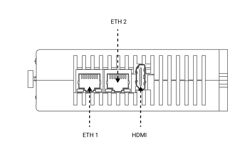
Communication interfaces
Ethernet
| Parameters | Specification |
|---|---|
| Ports | 2 x RJ45 |
| Port 1 | 10/100 Mbps |
| Port 2 | 0/100/1000 Mbps (native CM4) |
| Indicators | Link + ActivityLEDs |
RS-485
| Parameters | Specification |
|---|---|
| Mode | Half Duplex |
| Control | TX_EN Line |
| Minutes | Transparent/ any |
| Isolation | None |
USB
| Parameters | Specification |
|---|---|
| Ports | 2 |
| Type | USB-A |
| Standard | USB 2.0 Host |
| Maximum current | 400 mA per port |
| Protection | Overcurrent Protection |
HDMI
| Parameters | Specification |
|---|---|
| Ports | 1 |
| Connectors | Full-size HDMI |
| Maximum Resolution | Depends on CM4 and OS |
RF Communication
| Technology | Specification |
|---|---|
| Wi-Fi | Integrated with CM4 |
| BLE | Integrated with CM4 |
| LTE | M.2 NGFF Modem SIM7600G |
| SIM | External Access |
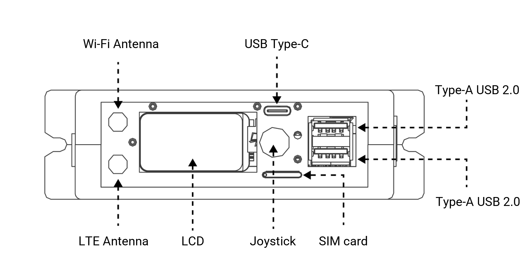
| #### Antenna connector | |
| Plugs | Use |
| --- | --- |
| RP-SMA | WLAN / BLE |
| SMA | LTE |
Local Peripherals
| Peripherals | Description |
|---|---|
| Temperature Sensor | Internal PCB Temperature Monitoring |
| Non-volatile memory | Persistent Storage |
| Safety IC | Microchip ATECC608A |
| RTC | Real-time clock with battery backup |
HDMI
1 Ad
| Parameters | Specification |
|---|---|
| Type | IPS TFT LCD |
| Interface | SPI |
| Size | 1.47" |
| Resolution | ≥ 172 x 320 |
| Backlight | LED |
| Assembly | Front-mounted with transparent window |
2 Joystick
| Parameters | Specification |
|---|---|
| Positions | 5 (Up/Down/Left/Right/Enter) |
| Type | Mechanical Tactile Switch |
| Interface | GPIO Expander |
Mechanical
| Parameters | Specification |
|---|---|
| Assembly | DIN Rail (EN 60715) |
| Enclosure | MAT0091092 (like iSense / iCee) |
| Protection Value | IP20 |
| Mounting Method | DIN Rail Snap-Fit |
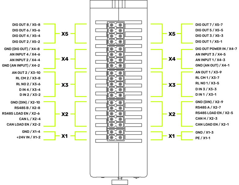
Connection
| Parameters | Specification |
|---|---|
| Connector Type | Pluggable System Terminal Block |
| Pitch | 3.5 mm |
| Layout | Double Row |
| Identification | Screen Printing with Side Panel |
| Fixation | Mechanical locking or spring clamp |
| Protection | Mechanical Reverse Protection |
Expansion
| Feature | Description |
|---|---|
| Piggyback Range | Reserved PCB Area |
| Compatibility | Fully compatible with existing FW |
| Available Drive Rails | Vin, 5 V, 3.3 V |
| Available Interfaces | 12C, SPI, UART, GPIO |
| External 1/0 Lines | 32 Leads Routed to External Connectors |
| Memory Expansion | M.2 NVMe SSD Connector |
Mechanical drawings
Front view
Ground view
Top view
System type
Raspian Debian GNU/Linux 13 (trixie) Version 13.2 Linux atlas 6.12.47 +rpt-rpi-v8 #1 SMP PREEMPT Debian 1 :6.12.47-1 +rpt1 (2025-09-16) aarch64 GNU/Linux.
Network information
There are three ways to connect to the device. IP and connection status can be checked on the LCD Network Interface.
Eth1 (ethO)
Client dynamic IP is obtained from the DHCP server.
Eth2 (eth1)
Static IP: 93.48.86.253
Access point (wlanO)
IP: 192.168.30.1
Installation
General information
- Mount the device on a DIN rail and supply it professionally (12–24 VDC).
- After power on, wait for boot; Network data can be displayed on the TFT network screen depending on the release.
- For initial access, use one of the following connections:
- ETH1 (DHCP)
- WLAN access point (SSID/password depending on serial number/release)
- ETH2 / service port (if active in the release, usually private subnet)
Mechanical installation
- Mounting on DIN rail (EN 60715)
- Protection class IP20 (installation in suitable control cabinet/environment)
- Mechanical drawings (front/floor/top view) see chapter "Technical data"
Electrical installation
- Connect power to 12-24 VDC (±5%).
- Lay cables in such a way that there is no tensile/crushing load.
- Perform I/O wiring according to technical specifications and project-specific design. Note: Detailed terminal/pin assignment is not yet fully included in the information provided and should be supplemented (terminal diagram/pinout).
Sensors
Interfaces / Peripherals (Overview)
Ethernet / WLAN
- ETH1: DHCP Client (Standard Access)
- WLAN-AP: SSID typically
iCee2-<SERIAL_NUMBER>-AP(password per release) - ETH2 / service port (release dependent): private subnet (e.g. called 192.168.50.0/24)
RS-485 (release dependent)
- RS-485 Serial Driver Interface available on
tty/AMA2(iCee2-CORE Release)
USB
- 2× USB host (test via SSH possible:
usb-devices)
CAN / CANopen (ATLAS)
- CAN controller: MCP2518FD (SPI)
- Encoder Reference: RM8007 (CANopen)
- Measurement rate (reference): approx. 500 measurements/s (estimation from bus cycle)
Note: Concrete connection diagrams/pinouts for RS-485/CAN/USB are only partially included in the supplied information (e.g. software examples), but should be supplemented for a complete hardware manual.
Software
Software Information
| Node-Red | Grafana | lnfluxDB | |
|---|---|---|---|
| Version | 4.1.4 | 12.3.1 | 2.8.0 |
| Port | 1880 | 3000 | 8086 |
| Condition | Clean | Clean | Clean |
| Authentication | None | User/Pass (Admin/Admin) | Undefined, configured the first time the interface is logged in. |
| GUI on | http:// |
http:// |
http:// |
MQTT Broker
Port: 1883
Address: AP-> 192.168.30.1
Eth1: 93.48.86.253
User: < not necessary>
Login
Relay outputs actor
App Interface
User app interface and functionalities available to the open part of the MQTT broker. Simplified interface for configuring and receiving peripheral data. The connection to the broker for this area does not require any access data.
Setting/resetting the digital output pin/pin status
Both relays default status is open.
Question topic: relayOutputs/config/in
{
  "id": "<TIMESTAMP>",
  "origin": "APP",
  "task": {
    "taskParams": {
      "D01": {
        "state": "open"
      },
      "D02": {
        "state": "open"
      }
    }
  }
}
{
  "id": "<TIMESTAMP>",
  "origin": "APP",
  "task": {
    "taskResult": {
      "D01": {
        "success": true,
        "state": "open"
      },
      "D02": {
        "success": true,
        "state": "open"
      }
    }
  }
}
Activate all relays
Request topic: relayOutputs/runtime/in
{
  "id": "<TIMESTAMP>",
  "origin": "APP",
  "task": {
    "action": "READ"
  }
}

Reply-Topic: relayOutputs/runtime/out

{
  "id": "<TIMESTAMP>",
  "origin": "APP",
  "task": {
    "taskResult": {
      "D01": {
        "success": true,
        "state": "open"
      },
      "D02": {
        "success": true,
        "state": "close"
      }
    }
  }
}
Set the state of all relays
Request topic: relayOutputs/runtime/in
{
  "id": "<TIMESTAMP>",
  "origin": "APP",
  "task": {
    "action": "SET",
    "taskParams": {
      "D01": {
        "state": "open"
      },
      "D02": {
        "state": "close"
      }
    }
  }
}
{
  "id": "<TIMESTAMP>",
  "origin": "APP",
  "task": {
    "taskResult": {
      "D01": {
        "success": true,
        "state": "open"
      },
      "D02": {
        "success": true,
        "state": "close"
      }
    }
  }
}
RTC Actor
App Interface
User app interface and functionalities available to the open part of the MQTT broker. Simplified interface for configuring and receiving peripheral data. The connection to the broker for this area does not require a vote of confidence.
Set timer/alarm clock interruption
Mode: Timer, alarm or not.
alarmSet: Date and time for alarm interruption (No effect whether the mode is timer or not).
timerSetSeconds: Period in seconds for timer interruption (no effect whether the mode is alarm or not).
Desired topic: Clock/Configuration/Setting
{
  "id": "<TIMESTAMP>",
  "origin": "APP",
  "task": {
    "taskParams": {
      "CLOCK\_SET\_MODE": {
        "mode": "timer",
        "alarmSet": "\[timestamp epoch ms\]",
        "timerSetSeconds": "<INT>"
      }
    }
  }
}
{
  "id": "<TIMESTAMP>",
  "origin": "APP",
  "task": {
    "taskResult": {
      "success": true,
      "CLOCK\_SET\_MODE": {
        "mode": "timer",
        "alarmSet": "\[timestamp epoch ms\]",
        "timerSetSeconds": "<INT>"
      }
    }
  }
}
Toggle RTC synchronization logic (described below)
tcState: State of the synchronization logic of the RTC, this value is non-persistent, so on each reboot the value reverts to the default (by default, the value is ON)
Desired topic: Clock/Configuration/Setting
{
  "id": "<TIMESTAMP>",
  "origin": "APP",
  "task": {
    "action": "TOGGLE"
  }
}

Req-Topic: clock/config/out

{
  "id": "<TIMESTAMP>",
  "origin": "APP",
  "task": {
    "taskResult": {
      "success": true,
      "rtcState": "OFF"
    }
  }
}
read-clock configurations
Mode: Timer, alarm or not.
alarmSet: Date and time for alarm interruption (No effect whether the mode is timer or not).
timerSetSeconds: Period in seconds for timer interruption (no effect whether the mode is alarm or not).
rtcState: Current state of the RTC's synchronization logic.
Desired topic: Clock/Configuration/Setting
Answer Topic: Clock/Configuration/Off{
"id": "<TIMESTAMP>",
"origin": "APP",
"task": {
"taskResult": {
"success": true,
"CLOCK\_CONFIGS": {
"mode": "timer",
"alarmSet": "\[timestamp epoch ms\]",
"timerSetSeconds": "<INT>",
"rtcState": "ON"
}
}
}
}
Reading Clock
Demand Topic: Clock/Runtime/In-Phase
{
"id": "<TIMESTAMP>",
"origin": "APP",
"task": {
"taskResult": {
"success": true,
"timestamp": "\[timestamp epoch ms\]"
}
}
}
Synchronization loop flowchart (every 30 seconds)
RTC Actor – Overview

Core System Health Actor
App Interface
User app interface and functionalities available to the open part of the MQTT broker.
This interface allows any external app to receive system metrics such as CPU load, RAM usage, disk usage, temperature, core frequency, system throttling status, and availability. No qualifications are required to subscribe to this topic. The System Health Actor does not receive any commands. It is completely autonomous and publishes its metrics every 1 second.
Runtime data
Topic: SystemHea l th/Runtime/ off
Release rate: 1 Hz (one message per second, clock jump for sure)
metrics provided
| Keys | Description | Unit |
|---|---|---|
| CPU_percent | Current CPU Load | % |
| CPU_tempC | CPU temperature read from Linux thermal zones | ºC |
| cpu0_freq | CPU Core O Current Frequency | Hz |
| cpul_freq | CPU Core 1 Power Frequency | Hz |
| cpu2_freq | CPU Core 2 Power Frequency | Hz |
| CPU3_freq | CPU Core 3 Power Frequency | Hz |
| CPU0_throttle | System Throttle Status Registry | Hex |
| Ram_percent | RAM Usage | % |
| disk_percent | Disk Usage for File System Root / | % |
| Uptime_sec\ | Time since the last restart | Seconds |
Example Payload (systemHealth/runtime/out)
{ "id": 1736022028123, "Origin": "System Health", "Task": { "taskResult": { "cpu_percent": 7.1, "CPU_tempC": 47.3, "CPU0_freq": 15000000000, "CPU1_freq": 15000000000, "CPU2_freq": 15000000000, "CPU3_freq": 1500000000, "cpu0_throttle": "0x0", "Ram_percent": 32.9, "disk_percent\": 41.2, "Uptime_sec": 5321 } } }
Peripheral Device Health
To maintain the health of the peripherals, we had to implement a SystemHealth actor in each bus manager (busi2cO, busi2c-1, etc.).

example
For busi2c-0:
Answer topic: systemHealth/busi2c-0/runtime/out
Payload:
{
"id": 1770378753024,
"origin": "system-health-busi2c-0",
"task": {
"taskResult": {
"ADC": {
"status": "ERROR",
"description": "IRQ Retrying",
"last\_report": 1770378753006,
"stats": {
"AI1": {
"samples": 563154,
"retries": 760548,
"discards": 253313
},
"AI2": {
"samples": 563154,
"retries": 760475,
"discards": 253314
},
"AI3": {
"samples": 563154,
"retries": 760528,
"discards": 253313
},
"AI4": {
"samples": 563154,
"retries": 760549,
"discards": 253312
}
}
},
"DAC": {
"status": "OK",
"description": "Running....",
"last\_report": 1770378752576,
"stats": {
"AO1": {
"samples": 240755,
"retries": 0,
"discards": 0
},
"AO2": {
"samples": 240755,
"retries": 0,
"discards": 0
}
}
},
"RTC": {
"status": "OK",
"description": "",
"last\_report": 1770378752094,
"stats": {
"samples": 248710,
"retries": 0,
"discards": 0
}
},
"TEMP": {
"status": "OK",
"description": "",
"last\_report": 1770378752579,
"stats": {
"samples": 240754,
"retries": 0,
"discards": 0
}
}
}
}
}
Answer topic: systemHealth/busi2c-1/runtime/out
Payload:
{
"id": 1770382405107,
"origin": "system-health-busi2c-1",
"task": {
"taskResult": {
"JOYSTICK": {
"status": "OK",
"description": "Running....",
"last\_report": 1770382405050,
"stats": {
"read\_all": {
"samples": 410154,
"retries": 0,
"discards": 0
},
"read\_raw": {
"samples": 0,
"retries": 0,
"discards": 0
},
"buttons": {
"JDOWN": {
"reads": 410154,
"last\_state": "pressed"
},
"JRIGHT": {
"reads": 410154,
"last\_state": "pressed"
},
"JUP": {
"reads": 410154,
"last\_state": "pressed"
},
"JLEFT": {
"reads": 410154,
"last\_state": "pressed"
},
"JCENTER": {
"reads": 410154,
"last\_state": "pressed"
}
}
}
},
"RELAYS": {
"status": "OK",
"description": "Relay Output MQTT connected",
"last\_report": 1770298859099,
"stats": {
"read\_all": {
"samples": 0,
"retries": 0,
"discards": 0
},
"set": {
"samples": 0,
"retries": 0,
"discards": 0
},
"set\_many": {
"samples": 0,
"retries": 0,
"discards": 0
},
"raw\_read\_all": {
"samples": 0,
"retries": 0,
"discards": 0
}
},
"outputs": {
"DO1": {
"writes": 0,
"last\_state": "unknown"
},
"DO2": {
"writes": 0,
"last\_state": "unknown"
}
}
},
"DI": {
"status": "OK",
"description": "Running",
"last\_report": 1770382404832,
"stats": {
"read\_all": {
"samples": 181758,
"retries": 0,
"discards": 0
},
"read\_raw": {
"samples": 0,
"retries": 0,
"discards": 0
},
"inputs": {
"DI1": {
"reads": 181758,
"last\_state": "low"
},
"DI2": {
"reads": 181758,
"last\_state": "low"
},
"DI3": {
"reads": 181758,
"last\_state": "low"
},
"DI4": {
"reads": 181758,
"last\_state": "low"
}
}
}
}
}
}
}
TempSensor Actor
App Interface
User app interface and functionalities available to the open part of the MQTT broker. Simplified interface for configuring and receiving peripheral data. The connection to the broker for this area does not require a vote of confidence.
Temperature sensor settings
Required Topic: tempSensor/config/in
ALARM:
- Activate: true(active)/false
- Temperature: Alarm temperature lower limit
- TemperatureHigh: Alarm temperature upper limit Answer topic: tempSensor/konfiguration/out Read ##### Temperature Sensor Configurations
Required Topic: tempSensor/config/in
ALARM:
- Activate: true(active)/false
LIMITS:
- Temperature: Alarm temperature lower limit
- TemperatureHigh: Alarm temperature upper limit Answer topic: tempSensor/konfiguration/out
View temperature and alarm status
- Unit: Temperature Unit
- Warning: true (triggered) or false
Required topic: tempSensor/Runtime
Answer topic: tempSensor/runtime/out{
"id": "<TIMESTAMP>",
"origin": "APP",
"task": {
"taskResult": {
"success": true,
"data": {
"temperature": <\_FLOAT\_>,
"unit": "C",
"alert": true
}
}
}
}
TFT Actor
App Interface
User app interface and functionalities available to the open part of the MQTT broker. Simplified user interface for controlling and interacting with the TFT display or LCD front panel. The connection to the broker for this area does not require any access data.
TFT Display Actor
The TFT actor is responsible for:
- Rendering static and informative screens on the TFT display
- Reagent on joystick input (LEFT/ RIGHT/ CENTER/ UP/ DOWN)
- Manage screen navigation and user confirmation flows
- Provide feedback to the application via MQTT
screen carousel concept
The TFT actor keeps an ordered list of screens (carousel).
- The screens are navigated with the joystick:
- LEFT --> Previous Screen
- CORRECT --> Next Screen
- The carousel wraps around:
- LEFT on the first screen --> last screen
- EXACTLY on the last screen --> first screen
screen types
The TFT actor supports the following screen types:
a.) Picture screen
- Displays a static JPEG image
- Default screen is displayed at startup
- No user interaction required
b.) Network Information Screen
- Display an interface with information about the device's networks
- Updated on load
- No user interaction required
joystick navigation logic
Carousel navigation:
| Joystick Input | Action |
| LINKS | Previous Screen |
| TRUE | Next Screen |
| DOWN | Update Current Screen |
boot behavior
For system boots:
- The TFT actuator initializes the display
- The last available carousel is loaded
- The first screen is rendered
- Joystick subscriptions will be activated
- The Actor Waits for Runtime Commands
Design Notes and Limitations
- TFT actor does not show joystick state freely
- Joystick actor remains independent
- TFT actor consumes joystick events internally
- Carousel State is local to the TFT actor
- Screen rendering is synchronous; Incoming treatment is carried out asynchronously
- Confirmation screens always require explicit CENTER printing
Interaction via MQTT
Enabling interaction with the carousel via the topic tft/runtime/in . Available actions are public to the user.
Runtime Commands
Go to the screen
Required topic: tft/runtime/in
{
"id": "<TIMESTAMP>",
"origin": "APP",
"task": {
"action": "SET\_CAROUSEL",
"params": {
"index": 2
}
}
}
{
"id": "TIMESTAMP",
"origin": "APP",
"task": {
"action": "SET\_CAROUSEL",
"params": {
"startIndex": 0,
"screens": \[
{
"type": "image",
"image": "default.jpg"
},
{
"type": "image",
"image": "status.jpg"
},
{
"type": "confirm",
"question": "Do you want to continue?"
}
\]
}
}
}
| Field | Description |
| Screens | Ordered List of Screens |
| Home lndex | Initial Active Screen (Optional, Default = 0) |
Answer
Answer topic: tft/runtime/out
{
"id": "TIMESTAMP",
"origin": "tft",
"task": {
"taskResult": {
"success": true,
"activeIndex": 0,
"totalScreens": 3
}
}
}
Analoglnputs Actor
App Interface
User app interface and functionalities available to the open part of the MQTT broker. Simplified interface for configuring and receiving peripheral data. The connection to the broker for this area does not require a vote of confidence.
configurations
Topic: analoglnputs/konfiguration/in – Setting ADC channel configurations
Mode
- continuous
- Single
Type
- Voltage
- current Answer topic: analoglnputs/config/out
Runtime Data
Topic: Analog Inputs/Runtime/In.
Action:
- READ
- PAUSE (only applicable in continuous mode)
- RESUME (only applicable in continuous mode) Answer Topic: Analog Inserts/Runtime/Off
Analog Output Actor
App Interface
User app interface and functionalities available to the open part of the MQTT broker. Simplified interface for configuring and receiving peripheral data. The connection to the broker for this area does not require a vote of confidence.
Setting Analog Output Signal
Desired topic: analogOutputs/config/in
Output: Current within 0-20 mA
Mode: On/Off
{
"id": "<TIMESTAMP>",
"origin": "APP",
"task": {
"taskParams": {
"mode": "on",
"AO1": {
"current": <\_FLOAT\_>
},
"AO2": {
"current": <\_FLOAT\_>
}
}
}
}
{
"id": "<TIMESTAMP>",
"origin": "APP",
"task": {
"taskResult": {
"mode": "on",
"AO1": {
"success": true,
"current": <\_FLOAT\_>
},
"AO2": {
"success": true,
"current": <\_FLOAT\_>
}
}
}
}
Setting Analog Outputs
Requirement Topic: Analog Expenditure/Duration
Current: Current within 0-20 mA
{
"id": "<TIMESTAMP>",
"origin": "APP",
"task": {
"taskParams": {
"AO1": {
"action": "SET",
"current": <\_FLOAT\_>
},
"AO2": {
"action": "SET",
"current": <\_FLOAT\_>
}
}
}
}
{
"id": "<TIMESTAMP>",
"origin": "APP",
"task": {
"taskResult": {
"AO1": {
"success": true,
"current": <\_FLOAT\_>
},
"AO2": {
"success": true,
"current": <\_FLOAT\_>
}
}
}
}
Reading Analog Output Settings
Requirement Topic: Analog Expenditure/Duration
Current: Current within 0–20 mA
{
"id": "<TIMESTAMP>",
"origin": "APP",
"task": {
"taskParams": {
"AO1": {
"action": "READ"
},
"AO2": {
"action": "READ"
}
}
}
}
{
"id": "<TIMESTAMP>",
"origin": "APP",
"task": {
"taskResult": {
"AO1": {
"success": true,
"current": <\_FLOAT\_>
},
"AO2": {
"success": true,
"current": <\_FLOAT\_>
}
}
}
}
Digital Input Actor
App Interface
User app interface and functionalities available to the open part of the MQTT broker. Simplified interface for configuring and receiving peripheral data. The connection to the broker for this area does not require any access data.
Adjust the speed of the digital input pins/pins quickly/slowly
The fast speed setting supports edge detection up to 100 Hz and the slow speed setting up to 10 Hz.
Quick Mode generates a message every time the I/O state changes, which can result in a high message payload during operation. Therefore, Quick Mode should only be enabled if absolutely necessary is required.
Prerequisite topic: digitallnputs/config/in
{
"id": "<TIMESTAMP>",
"origin": "APP",
"task": {
"taskParams": {
"DI1": {
"speed": "fast"
},
"DI2": {
"speed": "slow"
},
"DI3": {
"speed": "fast"
},
"DI4": {
"speed": "fast"
}
}
}
}
{
"id": "<TIMESTAMP>",
"origin": "APP",
"task": {
"taskResult": {
"DI1": {
"success": true,
"speed": "fast"
},
"DI2": {
"success": true,
"speed": "slow"
},
"DI3": {
"success": true,
"speed": "fast"
},
"DI4": {
"success": true,
"speed": "fast"
}
}
}
}
Get the status of all digital input pins.
Desired topic: digital entries/runtime
Answer Topic: digitalinputs/runtime/out state: high/low{
"id": "<TIMESTAMP>",
"origin": "APP",
"task": {
"taskResult": {
"DI1": {
"success": true,
"state": "high"
},
"DI2": {
"success": true,
"state": "low"
},
"DI3": {
"success": true,
"state": "high"
},
"DI4": {
"success": true,
"state": "low"
}
}
}
}
Digital Source Actor
App Interface
User app interface and functionalities available to the open part of the MQTT broker. Simplified interface for configuring and receiving peripheral data. The connection to the broker for this area does not require any declarations of faith.
Get the state of all digital output pins
Requirement topic: digitalOutputs/Runtime/in
Answer topic: digitalOutputs/Runtime/out{
"id": "<TIMESTAMP>",
"origin": "APP",
"task": {
"taskResult": {
"DO1": {
"success": true,
"state": "low"
},
"DO2": {
"success": true,
"state": "high"
},
"DO3": {
"success": true,
"state": "high"
},
"DO4": {
"success": true,
"state": "low"
},
"DO5": {
"success": true,
"state": "low"
},
"DO6": {
"success": true,
"state": "low"
},
"DO7": {
"success": true,
"state": "low"
},
"DO8": {
"success": true,
"state": "low"
}
}
}
}
Set the state of all digital output pins
Requirement topic: digitalOutputs/Runtime/in
{
"id": "<TIMESTAMP>",
"origin": "APP",
"task": {
"taskParams": {
"DO1": {
"action": "SET",
"state": "low"
},
"DO2": {
"action": "SET",
"state": "high"
},
"DO3": {
"action": "SET",
"state": "high"
},
"DO4": {
"action": "SET",
"state": "low"
},
"DO5": {
"action": "SET",
"state": "low"
},
"DO6": {
"action": "SET",
"state": "low"
},
"DO7": {
"action": "SET",
"state": "low"
},
"DO8": {
"action": "SET",
"state": "low"
}
}
}
}
{
"id": "<TIMESTAMP>",
"origin": "APP",
"task": {
"taskResult": {
"D01": {
"success": true,
"state": "low"
},
"D02": {
"success": true,
"state": "high"
},
"D03": {
"success": true,
"state": "high"
},
"D04": {
"success": true,
"state": "high"
},
"D05": {
"success": true,
"state": "high"
},
"D06": {
"success": true,
"state": "low"
},
"D07": {
"success": true,
"state": "low"
},
"D08": {
"success": true,
"state": "low"
}
}
}
}
Notes
If the Busi2c-3 is not powered, we will get the following:
Subject: Paragraph a lExpenditure/Duration/from
{
"id": "<TIMESTAMP>",
"origin": "APP",
"task": {
"taskResult": {
"DO1": {
"success": false,
"state": "DO\_not\_powered"
},
"DO2": {
"success": false,
"state": "DO\_not\_powered"
},
"DO3": {
"success": false,
"state": "DO\_not\_powered"
},
"DO4": {
"success": false,
"state": "DO\_not\_powered"
},
"DO5": {
"success": false,
"state": "DO\_not\_powered"
},
"DO6": {
"success": false,
"state": "DO\_not\_powered"
},
"DO7": {
"success": false,
"state": "DO\_not\_powered"
},
"DO8": {
"success": false,
"state": "DO\_not\_powered"
}
}
}
}
Joystick Actor
App Interface
User app interface and functionalities available to the open part of the MQTT broker. Simplified interface for configuring and receiving peripheral data. The connection to the broker for this area does not require a vote of confidence.
Get all joystick pins into state
Req-Topic: joystick/runtime/in
{
  "id": "<TIMESTAMP>",
  "origin": "APP",
  "task": {
    "action": "READ"
  }
}
{
  "id": "<TIMESTAMP>",
  "origin": "APP",
  "task": {
    "taskResult": {
      "JLEFT": {
        "success": true,
        "state": "pressed"
      },
      "JRIGHT": {
        "success": true,
        "state": "released"
      },
      "JUP": {
        "success": true,
        "state": "released"
      },
      "JDOWN": {
        "success": true,
        "state": "released"
      },
      "JCENTER": {
        "success": true,
        "state": "released"
      }
    }
  }
}
Included Software Stack

Hardware Libraries
[IMAGE PLACEHOLDER]
Related Products
| PA | Name | Requirements |
Accessories
| PA | Name | Requirements |
Document history
| Version | Description | Date |
| SBADATAv0.1 | First version of the i.Cee² datasheet | Nov 03, 2026 |
i.Cee² in the field
[IMAGE PLACEHOLDER]
Troubleshooting
Typical problems
No access to web interfaces - Check network (ETH1 DHCP / WLAN-AP / Service port) - Determine IP address via TFT network screen or router
Services not running (status)
- Check via SSH:
- systemctl is-active nodered
- systemctl is-active grafana-server
- systemctl is-active openvpn
- systemctl is-active mender-updated
USB devices are not recognized
- Check via SSH: usb-devices
- Test on both USB ports
FAQS
-
How do I find the IP address of the device?
Via the TFT network screen or via the DHCP server/router. -
How do I check if the basic services are running?
Via TFT status screen (if available) or via SSH withsystemctl is-active .... -
How is the serial number/hostname/access point set?
Via production scriptsetup-hostname-wlan-ap.sh <SERIAL_NUMBER>or (depending on release) via a UI mask with PIN and subsequent reboot.
Accessories
Accessories / Options (release dependent)
- SSD piggyback (NVMe) for storage expansion
- LTE modem (integrated, depending on variant/release)
- External antennas (SMA/RP-SMA, depending on the radio variant)
Abbreviation
- AP: Access Point
- DI/DO: Digital inputs/outputs
- AI/AO: Analog inputs/outputs
- RTC: Real Time Clock
- OTA: Over-the-Air Update
Explanation of terms
- Service port (ETH2): dedicated, private network interface (release dependent) for maintenance/service.
- Piggyback: Add-on module/expansion board (e.g. SSD or acquisition board).
Note: Circuit diagrams/terminal diagrams are not included in the information provided and must be supplemented on a project-specific basis.
Service / Maintenance
For support cases, please have ready:
- Device serial number / hostname
- Release/Version (TFT version screen, if available)
- short error description + photo/screenshot of the status screen
- (if available) excerpt of relevant systemctl checks
Documentation links (internal): - Production Procedures / Production manual - HW libraries MQTT API - Image Repository (SharePoint)
Service
Customer Service
de-smartplastics-service@igus.net
+49 (0) 2203 9649 9806
Technical support for igus® smart plastics
Documentation/FW
https://www.igus.de/info/i-sense-modul-2
Download manuals, FW updates and certificates
Smart Plastics website
https://www.igus.de/info/vorausschauende-wartung-smart-plastics
Possibility to order sensors, processing units and other accessories
Contact
Phone: +49 (0) 2203-9649-0F
Imprint
© 2026
All rights reserved.
igus® SE & Co. KG
Spicher Str. 1a
51147 Cologne