Manual
igus® smart plastics
i.Cee
Safety instructions
The following information boards will appear a few times in the manual, they are classified so that the degree and type of hazard are marked.
DANGER!
Safety instructions marked DANGER indicate an imminent danger situation.
WARNING!
Safety instructions marked with WARNING indicate a possible dangerous situation. Ignoring the notice may lead to a serious or even fatal accident or property damage.
CAUTION!
Safety instructions marked with CAUTION indicate a possible dangerous situation. Failure to comply with the notice may lead to an accident or property damage.
NOTE!
Safety instructions marked with NOTE indicate a possible dangerous situation. Failure to comply with the notice may lead to property damage. General information and explanations are also marked in this way.
WARNING!
i.Cee.plus II is not a safety component within the meaning of the Machinery Directive and does not provide protection against personal injury. Failure to do so can lead to serious property damage and personal injury.
Qualified personnel
The i.Sense:modul II may only be operated and maintained by qualified specialists.
-
The staff must have read and understood this manual and any additional documentation that may exist.
-
Personnel must be familiar with all relevant applicable standards, regulations and accident prevention regulations.
-
The personnel must be able to foresee or recognize any hazards that may arise when using the controls.
-
Personnel must be able to ensure the safety of people and objects when using the sensor unit in the overall system.
-
Personnel must be trained in the handling of ESD sensitive equipment and must have all necessary Take precautions.
Compliance with EU Directives
The CE marking on the device confirms compliance with the following European directives:
| Policy | Description |
|---|---|
| 2014/30/EU Electromagnetic Compatibility (EMC) | Directive of the European Parliament and of the Council on the harmonisation of the laws of the Member States relating to electromagnetic compatibility |
| 2014/53/EU | Directive of the European Parliament and of the Council on the harmonisation of the laws of the Member States relating to the making available on the market of radio equipment and repealing Directive 1999/5/EC |
| 2011/65/EU RoHS | Directive of the European Parliament and of the Council on the restriction of the use of certain hazardous substances in electrical and electronic equipment |
The applicable directives are listed in the EU declaration of conformity of the respective device.
Cyber Resilience Act (CRA) Notice
This product contains digital components. For such products, the Security requirements of the EU Cyber Resilience Act (Regulation (EU) 2024/2847). The CRA specifies that software and connected devices must be used across the entire life cycle must be operated safely and kept up to date.
To ensure that you can use your system reliably and safely, please note:
- Install deployed firmware and software updates regularly.
- Use secure network and access settings.
- Change default passwords immediately after commissioning.
- Disable unnecessary interfaces or services.
If you see a technical anomaly or a possible security vulnerability , please report them via the official igus support channel: security@[manufacturer].com or via the service portal.
The CRA also requires users to have access to information on: Receive security support, known risks, and update processes. For more details, please refer to the documentation of this product or with your national market surveillance authority.
Note on the EU Dual-Use Regulation (EU) 2021/821
Individual electronic components and sensors in this product may vary depending on the fall under the EU Dual-Use Regulation (EU) 2021/821. This ordinance regulates goods that are used in both civilian and military area.
For export to countries outside the EU, a permit can therefore be obtained may be necessary. Whether this is true depends on the target market, the application and the respective technical configuration.
Please check before passing on or exporting the product:
- whether there are export restrictions for your destination country,
- whether your application is considered security-critical or military-grade,
- whether a permit is required under applicable regulations.
For more information, please contact your national export control authority (e.g. BAFA in Germany) or in the official EU documents.)
Maintenance
i.Cee:plus II is maintenance-free. Apart from the connectors, the i.Cee:plus II does not contain any components that can be replaced by the user. If hardware problems occur, please contact the Kundenservice (S.26).
Electromagnetic compatibility
WARNING!
- Risk of injury due to interference with signals and equipment Disturbed signals can cause unforeseen device actions. Carry out the wiring according to the EMC measures. Failure to comply with these precautions may result in death, serious injury or material damage.
| Measures on EMC |
Impacts |
|
|---|---|---|
| Device Assembly |
Use cable clamps for shield support, connect metallic parts over a large area |
Good conductivity due to flat contact |
| Supplement switchgear such as contactors, relays or solenoid valves with interference suppression combination or spark extinguishing elements (e.g. diodes, varistors, RC links). |
Reduce mutual interference coupling. |
|
| Wiring |
Keep cables/connections as short as possible |
Avoiding capacitive and inductive interference |
| Do not lay sensor cables and signal cables together with cables for DC and AC voltage above 60 V in a cable duct. |
Avoidance of mutual interference coupling |
|
| Ground shields of digital signal lines on both sides over a large area or via conductive connector housings. |
Avoid interference with control cables, reduce emissions. |
Product Overview
Betriebsarten
| Operating mode |
Description |
|---|---|
| Online |
- Data comparison for predictive maintenance with those determined by igus® in the laboratory - Remote access to user interface - Connection to the Internet required |
| Offline |
- Previously stored information is used for predictive maintenance recommendations - Operates without connection to the Internet |
Technische Data
| Mechanical Specifications | |
|---|---|
| D x W x H in millimeters incl. plugs & fasteners |
110 x 31 x 125 mm |
| Weight in grams |
Approx. 120 g |
| Fastening/Mounting |
On TS35 Carrier Rail in Grounded Metal Control Cabinets |
| Colour |
black |
| Connectable conductor cross-section |
0.25... 1.5 mm2 |
CAUTION!
- Risk of destruction
: An operating voltage above the voltage specified in the specifications will destroy the i.Cee:plus II.
CAUTION!
The device is intended for installation in a grounded control cabinet. If this is disregarded, function and health may be endangered. The function earthing system should definitely be connected.
| Electrical Specifications | |
|---|---|
| Power supply |
24 V DC |
| Rated current |
1 A |
| Maximum input on digital pins X2 |
3.3 V DC |
| Environmental conditions | ||
|---|---|---|
| Temperature range | Operations | -20… 40 °C |
| Storage | -40... 45 °C | |
| Transport | -40... 45°C | |
| Relative humidity | ≤ 90%, non-condensing | |
| Degree of protection | IP 30/ DIN EN 60529 |
WARNING!
- Risk of malfunction
- Fire hazard
- Risk of explosion
- Risk of electric shock
- Fire hazard
Do not operate i.Cee:plus II in water, humid environments or in aggressive, flammable or explosive atmospheres.
Installation
Elektrische Installation
WARNING!
- Risk of electric shock
- Risk of electric arcs
- Risk of injury
- Risk of component destruction
Always turn off the power supply before disconnecting or making electrical connections in the system. Secure the power supply against reconnection. After switching off, wait at least 5 minutes for the capacitors to discharge. Check the absence of voltage before working in the system. Occurrence of arcs in the case of electrical connections that are not installed properly. Cables connected to i.Cee:plus II must not have exposed and stripped wire ends. Also, ensure that all connections are securely seated.
CAUTION!
The terminals are designed for single wires only.
Due to improper multiple occupancy, a fixed connection cannot be guaranteed. There is a risk that wires can slip out of the terminals and cause short circuits.
If several signals/wires have to be connected to a connection terminal, they must be merged via an external terminal and connected from there with a single wire.
Auswahl of Power Supply
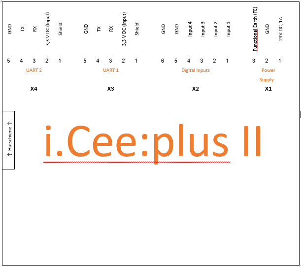
Information on the correct dimensioning of the voltage source can be found in the technical data. To connect these, use the pins to X1. A Zeichnung where these can be found can be found under 4.2.2 (p.9).
| Clamp |
Designation |
|---|---|
| X1 – 3 |
PE |
| X1 – 2 |
GND |
| X1 – 1 |
+24V |
CAUTION!
Do not turn on the power supply until all other components have been connected. If this is not observed, there is a possibility of electric shock or malfunction of the connected component.
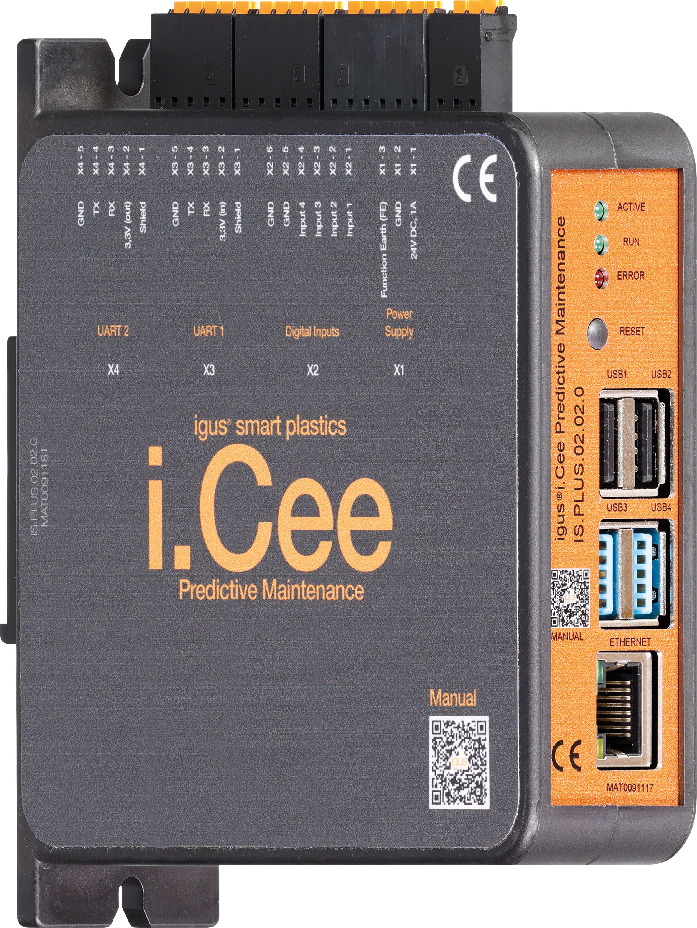
Steckerbelegung and sensor connection
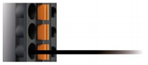
The plug connections run according to the scheme as described below:
- Press the orange spring of the respective wire opening into the plug with your hand or pliers and hold it there.
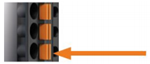
- Push the stripped wire about 9mm deep into the opening.
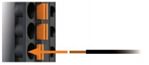
- Let the orange spring come out of the plug again. Check the secure fit of the strand.
Housing with labeling of the connectors
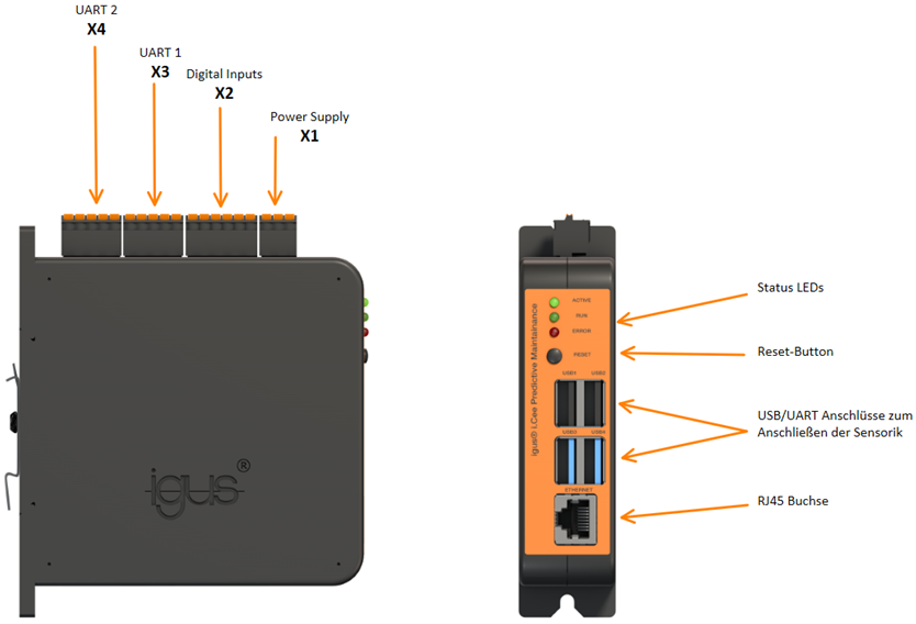
Connection diagram of the module
Connection of the sensors
Sensors are connected to i.Cee:plus II in four ways:
1) By UART/USB
2) Through i.Sense or i.Sense:modul II, connection to i.Cee:plus II via USB.
3) Free use of X2 digital inputs, such as plain bearings, abrasion sensors, is also possible.
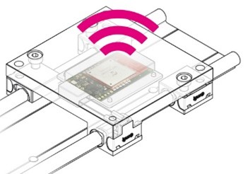
4) By wireless technology (W-LAN, LoRa, Bluetooth, etc.)
Caution
Failure to observe the maximum input values on the digital inputs can lead to malfunctions and the destruction of i.Cee:plus II. This can result in personal injury.
NOTE!
When connecting a conductor loop to digital inputs X2, input active if conductor loop is interrupted.
Kommunikationsschnittstellen
Connection of the UART interfaces
Connection of the UART interfaces to X3 and X4
| Clamp |
Designation |
Color |
|---|---|---|
| X3/X4 – 5 |
GND |
black |
| X3/X4 – 4 |
TX |
Yellow |
| X3/X4 – 3 |
RX |
Orange |
| X3/X4 – 2 |
3.3V |
Red |
| X3/X4 – 1 |
Umbrella |
Metal Mesh |
CAUTION!
Be sure to connect the shield of the cables. Otherwise, function and health may be at risk.
Sensors
Anschluss Wear sensors EC. W/EC.IT & roller chain link, as well as plain bearing wear sensors
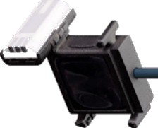
LoRa recipient
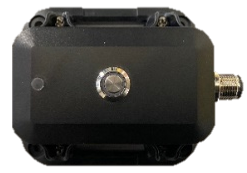
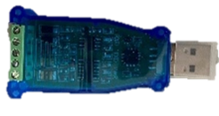
Receiver module (upper image) for igus® sensor signals sent via LoRa radio technology Connection: RS485-> USB converter (bottom picture) on USB inputs of the i.Cee:plus II Description of the connection in the manual to the IS. LORA.22.18.0.BETA
EC.IT - Monitoring of bolt/bore wear of an igus® e-chain®
-005da20d-1149-45a3-bb76-26f18391a660.jpg)
Quality monitoring of bolts and bore of an igus® e-chain® by means of a replica chain link used as a separator in e-chain® for the E2 to E4/P4 series with a maximum inner height of 112mm Connection: Via LoRa receiver under 5.1.1
EC. W – Wear monitoring for igus® e-chain®
Quality monitoring on the inside of an igus® e-chain® with intelligent separator in e-chain® for the E2 to E4 series with a maximum internal height of 112mm Connection: Wired via UART
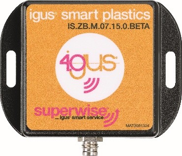
Zustandsüberwachung to drylin® linear guides
Wear detection for linear guides from igus® Connection: Via LoRa receiver under 5.1.1
ComBox
Mobile modem for sending error messages Connection: - UART terminals on i.Cee:plus II - Four-wire, M8 screw connectors
Anschluss other sensors i.Sense:modul II
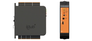
Microprocessor-based DIN rail module for continuous evaluation of connected i.Sense sensors and part of the igus® smart plastics condition monitoring concept Special features: i.Sense:modul II has its own user interface, accessible via the IP address or https address of i.Cee:plus II followed by "/isense/"
Connection: Micro-USB-> USB-A cable to USB inputs of the i.Cee:plus II User Interface Accessible by adding "/isense/" to the browser address
Inbetriebnahme and user interface
Troubleshooting
- Unable to connect to the user interface
o Try again
o Restart devices and then try again
o If that doesn't help, contact the Kundenservice (S.26)
- The device does not determine all sensor data, what now?
o Check all connectors and restart the system.
o If that doesn't help, contact the Kundenservice (S.26)
FAQS
- What are the LEDs for?
o At the moment they have no function.
- How are the sensor limits set?
o It is advisable to use a programmer for help.
o The individual steps can be found under the heading Description of the backend interface.
- How do you retrieve the sensor data obtained?
o Under the item User Interface, the individual steps for operating the user interface are listed.
Accessories
Abbreviation
Explanation of terms
Service
Customer Service
de-smartplastics-service@igus.net
+49 (0) 2203 9649 9806
Technical support for igus® smart plastics
Documentation/FW
https://www.igus.de/info/i-sense-modul-2
Download manuals, FW updates and certificates
Smart Plastics website
https://www.igus.de/info/vorausschauende-wartung-smart-plastics
Possibility to order sensors, processing units and other accessories
Contact
Phone: +49 (0) 2203-9649-0F
Imprint
© 2026
All rights reserved.
igus® SE & Co. KG
Spicher Str. 1a
51147 Cologne