Manual
igus® smart plastics
i.Sense
Safety
Read this manual completely before commissioning and observe all safety and installation instructions. If integrated into an overall system, this information must be passed on to the end user.
Warranty applies only in accordance with the specifications stated in this manual and is limited to repair or replacement of the i.Sense. igus® accepts no liability for integration tasks, consequential damages, misuse, or unauthorized modifications; the right to make changes to the product and documentation is reserved.
The i.Sense may only be operated if the safety and installation instructions are observed, the housing is mounted in compliance with ESD/EMC requirements, the device is unmodified and in perfect condition, and the operating limits specified in the technical data are adhered to.
Please provide the text you'd like me to translate.
Qualified Personnel
The i.Sense may only be operated and maintained by qualified specialist personnel.
-
Personnel must have read and understood this manual and any additional documentation that may exist.
-
Personnel must be familiar with all relevant applicable standards, regulations, and accident prevention regulations.
-
Personnel must be able, through their training, to anticipate or recognize potential hazards that may arise during use of the system.
-
Personnel must be able to ensure the safety of persons and objects when using the sensor unit in the overall system.
-
Personnel must be trained in the handling of ESD-sensitive devices and must take all necessary precautions.
Please provide the text you'd like me to translate.### Intended Use
Purpose and Scope
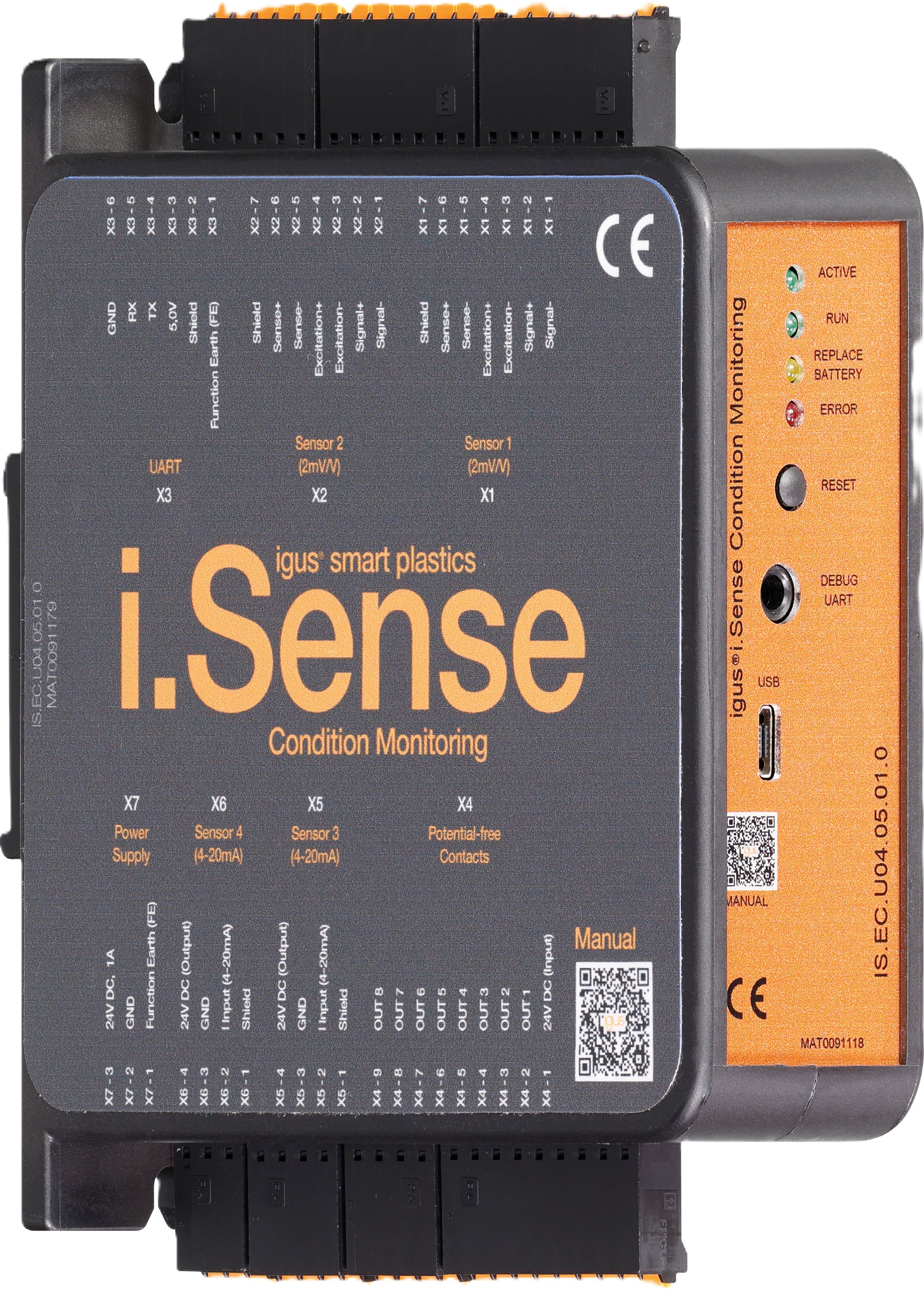
- i.Sense:modul II is a microprocessor-based DIN rail module (diagnostic tool) for the continuous evaluation of connected i.Sense sensors.
- The goal is the detection of unusual operating conditions (e.g. blockage/breakage) on igus® e‑chain systems®, in order to avoid unplanned machine downtime.
- Via eight potential-free contacts, a rapid machine response to unexpected operating conditions can be triggered.
- Configuration and sensor data download are performed via USB and WiFi.
DANGER!
i.Sense:modul II is not a safety component within the meaning of the Machinery Directive and is not suitable for preventing personal injury during machine/plant operation.
The device is intended exclusively for preventing blockages or breakages on igus® e‑chain systems®.
If disregarded, serious personal injury up to and including death, severe irreversible injuries, and material damage are possible.
Requirements
- Use the device exclusively in accordance with its intended use. The protection of persons is not guaranteed if the device is not used as intended.
- igus® GmbH accepts no liability for damages arising from use other than the intended use.
- Read this original operating manual before commissioning. Knowledge of the original operating manual is part of the intended use.
Foreseeable Misuse
- Any use other than that specified under "Intended Use" or any use beyond that scope shall be considered unintended use.
The following uses are not permitted, in particular
- in safety-relevant circuits
- in rooms with explosive atmospheres
- on machines and plants with vibrationsPlease provide the text you'd like me to translate.
IMPORTANT: Update firmware regularly
The i.Sense module must be regularly updated to the current firmware version.
An outdated firmware version can lead to malfunctions, limited diagnostic capability, or unexpected behavior.
The procedure is described in the Firmware-Update durchführen section.
Please provide the text you'd like me to translate.
The following notice boards will appear several times in the manual. They are classified so that the degree and type of hazard are indicated.
DANGER!
Safety notices marked with DANGER indicate an immediate hazardous situation.
WARNING!
Safety notices marked with WARNING indicate a potential hazardous situation. Failure to observe the notice may result in a serious or even fatal accident or property damage.
CAUTION!
Safety notices marked with CAUTION indicate a potential hazardous situation. Failure to observe the notice may result in an accident or property damage.
NOTE!
Safety notices marked with NOTE indicate a potential hazardous situation. Failure to observe the notice may result in property damage. General notes and explanations are also marked in this way.
Product Overview
Operating Modes
| Operating Mode |
Description |
|---|---|
| Stand- Alone |
- Detection of unusual operating conditions on igus® e-chain systems® - Connection of up to 4 sensors (2x force sensor/load cell, 2x position sensor (4-20mA) - Sensor configuration as well as adjustments to measurement algorithms and sensitivity via graphical user interface through USB and WLAN - Raw data storage in internal eMMC memory - Raw data download in CSV format and as SQL database - Connection to machine control via normally closed contacts for connection to I/O ports - Optional: Notification of threshold exceedances and alarm messages via SMS |
| Hybrid |
- Predictive maintenance information (additional connection to i.Cee II required) - Possibility of display in dashboard in online and offline operation |
Table 2: Product Overview
Please provide the text you'd like me to translate.
Technical Data
| Mechanical Specifications | |
|---|---|
| D x W x H in millimeters incl. connectors & fasteners |
110 x 31 x 125 mm |
| Weight in grams |
Approx. 120 g |
| Mounting / Installation |
TS35 DIN rail in grounded metal control cabinets |
| Color |
Black |
| Connectable conductor cross-section |
0.25…1.5 mm2 (uninsulated ferrules) 0.25…0.75 mm² (insulated ferrules) 0.25…1.5 mm² (without ferrule) |
Table 3: Mechanical Specifications
CAUTION!
- Risk of destruction
An operating voltage that exceeds the voltage specified in the technical data will destroy the . Select an operating voltage that is within the voltage range specified in the technical data.
Please provide the text you'd like me to translate.
| Electrical Specifications | |
| --- | --- |
| Power supply (terminal X7)
| 24V DC (1A max.)
|
| Power supply potential-free contacts (terminal X4)
| 24V DC (0.3A max.)
|
| Output voltage (terminal X1 and X2)
| 5V DC
|
| Output voltage (terminal X3)
| 5V DC (0.5A max.)
|
| Output voltage (terminal X5 and X6)
| 24V DC
|
| Residual ripple | 100mV pp |
Table 4: Electrical Specifications
| Interfaces | |
|---|---|
| UART |
5V (0.5A max.) Output, 115200 baud, 8N1, no parity |
| Service UART (3.5mm jack) |
3.3V Input, 115200 baud, 8N1, no parity |
| RS-485 |
proprietary |
| Bluetooth |
4.0 dual mode |
| WLAN |
802.11b/g/n |
| Ethernet |
100 Mbit/s |
Table 5: Interfaces
| Storage Capacity | |
|---|---|
| Sensor data storage |
4GB ring buffer of 8GB eMMC |
Table 6: Storage Capacity
Please provide the text you'd like me to translate.
WARNING!
- Risk of malfunction
- Risk of fire
- Risk of explosion
- Risk of electric shock
Do not operate the i.Sense:modul II in water, in humid environments, in aggressive, flammable or explosive atmospheres, or under vibration. Due to the self-heating of the device, it must be ensured that the ambient temperature does not exceed 40°C. If this cannot be guaranteed, a ventilated or air-conditioned enclosure must be used.
| Ambient conditions | ||
|---|---|---|
| Temperature range | Operation | -20…40 °C |
| Storage | -40…45 °C | |
| Transport | -40…45°C | |
| Relative humidity | ≤ 90%, non-condensing | |
| Protection class | IP 20/ DIN EN 60529 |
Table 7: Ambient conditions
Installation
CAUTION!
Always route the device's connection cables outside of traffic areas. Loosely routed cables pose a tripping hazard. Do not route cables over sharp edges, corners, or moving parts, or allow them to become pinched. No objects may be hung or attached to cables. Electrical equipment must be handled with care. Flexible cables and plugs must be protected from damage caused by pinching, impact, and being run over by vehicles and equipment. Electrical devices, cables, and connectors may only be used if they meet the operational and local safety requirements with regard to the type of operation and environmental influences.
Please provide the text you'd like me to translate.
Mechanical Installation
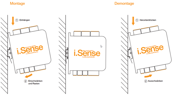
- Vertical, TS35 DIN rail
- Vibration-free mounting location
- Connection space: 50mm vertical, 35mm
- Avoid heat build-up, ensure adequate ventilation
Please provide the text you'd like me to translate. Electrical Installation
WARNING!
Switch the device off immediately if it is damaged (including the connecting cables) or if faults or unusual phenomena occur (e.g. arcing, sparks, smell of burning, unusual noises). In this case, the device must be taken out of service immediately.
- Disconnect all electrical power sources.
- Do not attempt to repair the device yourself.
- Report defects immediately to your supervisor, warn others, and contact the igus® branch responsible for your country.
Possible hazards: - Risk of electric shock - Risk of arcing - Risk of injury - Risk of component damage
Always switch off the power supply before disconnecting or establishing electrical connections in the system. Secure the power supply against being switched back on.
If electrical connections are not properly installed, arcing may occur. Cables connected to i.Sense:modul II must not have any exposed or stripped wire ends. Also ensure that all connections are securely seated.
CAUTION!
The terminal connectors are designed for single conductors only. Improper multiple connections cannot guarantee a secure connection. There is a risk that conductors may slip out of the terminal connectors, causing short circuits.
If multiple signals/conductors need to be connected to a single terminal connector, the consolidation must be achieved via an external terminal and connected from there using a single conductor.
Power Supply
| Terminal |
Designation |
|---|---|
| X7 – 3 |
+24V DC |
| X7 – 2 |
GND |
| X7 – 1 |
FE (Functional Earth) |
| X3 – 1 |
FE (Functional Earth) |
Table 8: Power Supply
| Connector Assignment and Sensor Connection | |
|---|---|
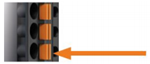
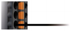
| 1. Press the orange spring of the respective wire opening into the connector by hand or with pliers and hold it there. |
 |
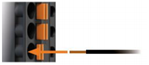
| 2. Insert the wire into the opening up to the stop. |
 |
| 3. Release the orange spring so it extends back out of the connector. Check that the stranded wire is securely seated. |
 |
NOTE!
Permissible connection cross-sections:
- 0.25…1.5 mm² (uninsulated ferrules)
- 0.25…0.75 mm² (insulated ferrules)
- 0.25…1.5 mm² (without ferrule)
Figure 2: Connector Assignment and Sensor Connection
Connections, LEDs and Buttons
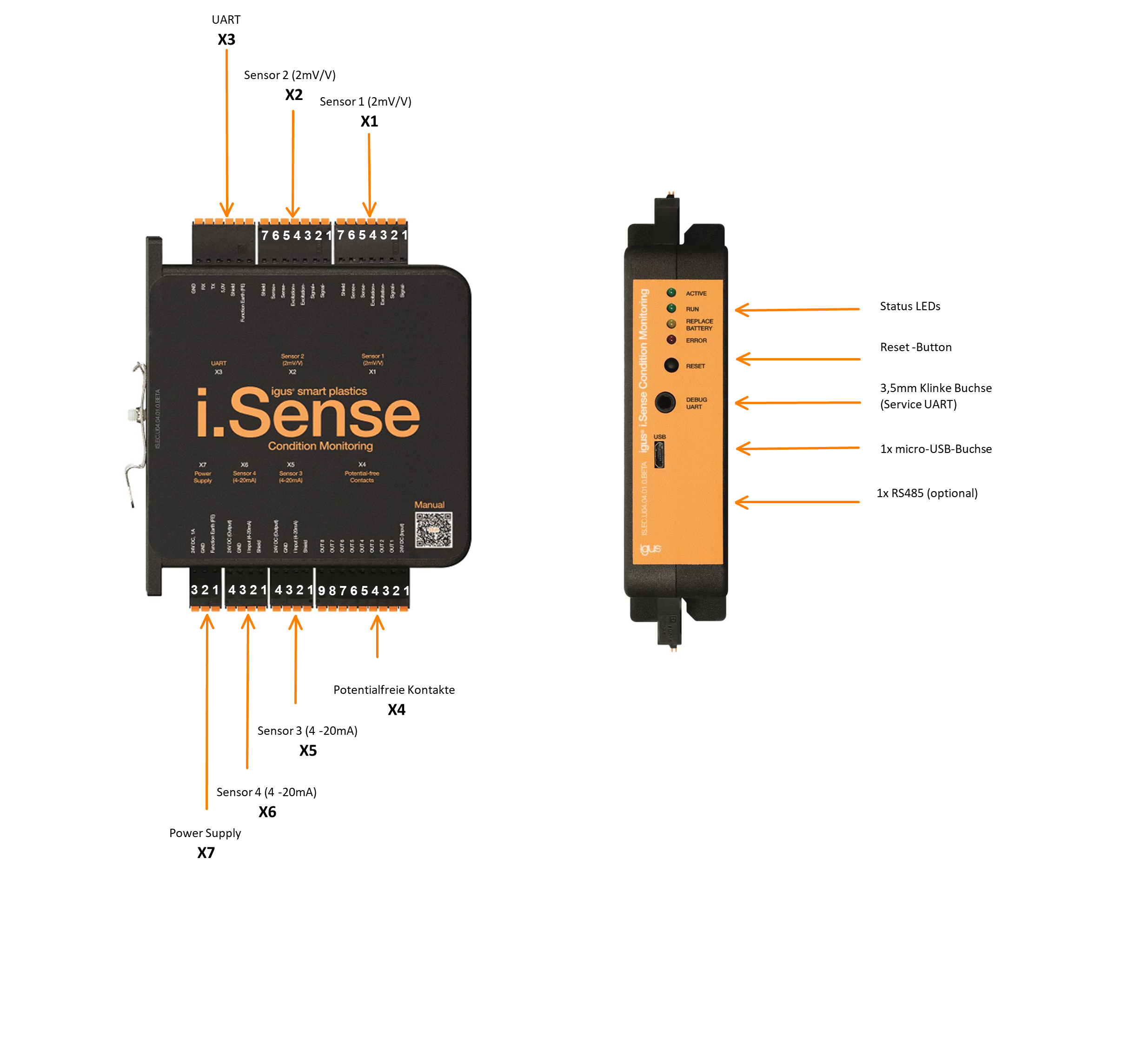
Wiring Diagram
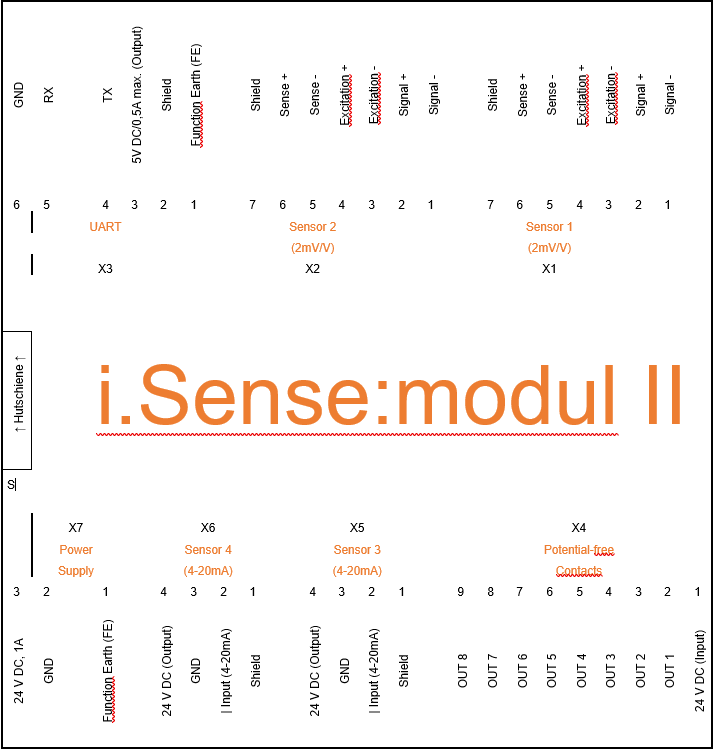
Potential-Free Contacts
| Terminal |
Designation |
Definition |
|---|---|---|
| X4 – 9 |
OUT 8 |
Reserve |
| X4 – 8 |
OUT 7 |
Reserve |
| X4 – 7 |
OUT 6 |
Reserve |
| X4 – 6 |
OUT 5 |
Reserve |
| X4 – 5 |
OUT 4 |
Fault contact sensor 4 |
| X4 – 4 |
OUT 3 |
Fault contact sensor 3 |
| X4 – 3 |
OUT 2 |
Fault contact sensor 2 |
| X4 – 2 |
OUT 1 |
Fault contact sensor 1 |
| X4 – 1 |
24V DC (Input) |
Power supply fault contacts |
Table 9: Potential-Free Contacts
Schematic Diagram: Connection of Potential-Free Contacts to Customer Control System
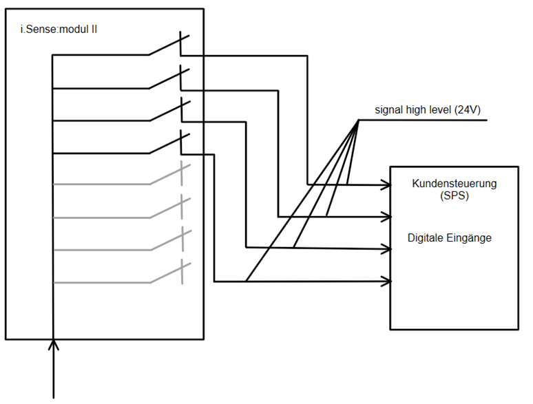
Figure 5: Schematic Diagram: Connection of Potential-Free Contacts to Customer Control System
Communication Interface
Connection of the UART Interface
Connection of the ComBox
| Terminal |
Designation |
|---|---|
| X3 – 6 |
GND |
| X3 – 5 |
RX |
| X3 – 4 |
TX |
| X3 – 3 |
5V |
| X3 – 2 |
Shield |
Table 10: UART Interface
Sensors
CAUTION!
The device is designed to monitor forces up to a maximum of 90% of the rated load. For simplicity, a mass of 1t corresponds to a force of 10000N and a mass of 2t corresponds to a force of 20000N. When using a load cell with a rated capacity of 1t and 2t, the following maximum adjustable force limit values apply (see Table 1). Setting force limit values beyond 90% of the rated capacity is not permitted.
| Rated capacity load cell | Maximum adjustable force limit values 90% of rated capacity |
|---|---|
| 1t | 9000 N |
| 2t | 18000 N |
Table 11: Maximum adjustable force limit values
Terminals X1/X2 2mV/V Force Measurement
igus® Strain Gauge Sensors for Tension-Compression Force Measurement on igus® e-chain systems®:
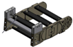 Figure 6:
Strain gauge sensor on KMA
Strain gauge (SG) sensor in a set with a second "dummy" for mounting on igus® KMA connection elements for e-chain systems® of series E2, E4, P4
Connection: Four-wire, M12 industrial connector
Pin assignment: igus® strain gauge sensors with CF10.03.05.INI cable
| Terminal | Designation | Wire colors when using a CF.10.03.05.INI force sensor cable |
|---|---|---|
| X1/X2 – 7 | Shield | Shield (yellow) |
| X1/X2 – 6 | + Sense | -- |
| X1/X2 – 5 | - Sense | -- |
| X1/X2 – 4 | + Excitation | white |
| X1/X2 – 3 | - Excitation | black |
| X1/2 – 2 | + Signal | blue |
| X1/X2 – 1 | - Signal | brown |
Table 12: Connection Terminal X1 / X2
Load cells integrated in floating carriers
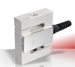
Figure 7:
Vishay load cell Model 616 1t
Load cells integrated in the metal structure of the floating carrier for all igus® e-chain systems®
Connection: Seven-wire, Harting HAN 3A M20 EMC industrial connector
Pin assignment: Vishay load cell Model 616, 1t
| Terminal | Designation | Wire colors of the 3m connection cable |
|---|---|---|
| X1/X2 – 7 | Shield | Shield (yellow) |
| X1/X2 – 6 | + Sense | Blue |
| X1/X2 – 5 | - Sense | brown |
| X1/X2 – 4 | + Excitation | green |
| X1/X2 – 3 | - Excitation | black |
| X1/X2 – 2 | + Signal | red |
| X1/X2 – 1 | - Signal | white |
Table 13: Connection Vishay load cell Model 616 1t to Terminal X1 / X2
Pin assignment: Vishay load cell Model 620, 2t
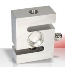
Figure 8:
Vishay load cell Model 620 2t
| Terminal | Designation | Wire colors of the 5m connection cable |
|---|---|---|
| X1/X2 – 7 | Shield | Shield |
| X1/X2 – 6 | + Sense | green |
| X1/X2 – 5 | - Sense | grey |
| X1/X2 – 4 | + Excitation | blue |
| X1/X2 – 3 | - Excitation | black |
| X1/X2 – 2 | + Signal | White |
| X1/X2 – 1 | - Signal | Red |
Table 14: Connection Vishay load cell Model 620 2t to Terminal X1 / X2
Load cells integrated in cable pull force sensors
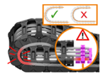
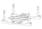
Load cells (as in floating carrier) integrated in the metal structure of the strain relief for igus® e-chain systems® of series E4.42, E4.56, E4.80, 4040, 5050, P41.56, P41.80
Connection: Eight-wire, Harting HAN 3A M20 EMC industrial connector
Pin assignment: Vishay load cell Model 616, 1t
| Terminal | Designation | Wire colors of the 3m connection cable |
|---|---|---|
| X1/X2 – 7 | Shield | Shield (yellow) |
| X1/X2 – 6 | + Sense | Blue |
| X1/X2 – 5 | - Sense | brown |
| X1/X2 – 4 | + Excitation | green |
| X1/X2 – 3 | - Excitation | black |
| X1/X2 – 2 | + Signal | red |
| X1/X2 – 1 | - Signal | white |
Table 15: Connection Vishay load cell Model 616 1t to Terminal X1 / X2
Pin assignment: Vishay load cell Model 620, 2t
| Terminal | Designation | Wire colors of the 5m connection cable |
|---|---|---|
| X1/X2 – 7 | Shield | Shield |
| X1/X2 – 6 | + Sense | green |
| X1/X2 – 5 | - Sense | grey |
| X1/X2 – 4 | + Excitation | blue |
| X1/X2 – 3 | - Excitation | black |
| X1/X2 – 2 | + Signal | White |
| X1/X2 – 1 | - Signal | Red |
Table 16: Connection Vishay load cell Model 620 2t to Terminal X1 / X2
Pin assignment: ME-Messsysteme load cell KD40s, 200kg
| Terminal | Designation | Wire colors of the 3m connection cable |
|---|---|---|
| X1/X2 – 7 | Shield | Shield |
| X1/X2 – 6 | + Sense | -- |
| X1/X2 – 5 | - Sense | -- |
| X1/X2 – 4 | + Excitation | brown |
| X1/X2 – 3 | - Excitation | white |
| X1/X2 – 2 | + Signal | green |
| X1/X2 – 1 | - Signal | yellow |
Table 17: Connection ME-Messsysteme load cell Model KD40s 200kg to Terminal X1 / X2 Principle of cable pull force sensor Structure of cable pull force sensor
Please provide the text you'd like me to translate.
CAUTION!
The device is designed to measure positions within the nominal length. When using a position sensor with a 99mm nominal length, the lower position limit must be >0mm (e.g. 10mm), the upper position limit must be <99mm (e.g. 90mm). Setting position limits <= 0mm for the lower position limit and >= 99mm for the upper position limit is not permitted. The same applies to position sensors with other nominal lengths.
Terminals X5 / X6 4-20mA
Breaking Force Sensor Integrated in SLS Housing
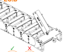
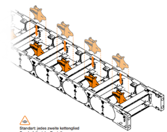
Figure 11:
Breaking Force Sensor Assembly
Breaking force monitoring on the floating carrier for mounting on igus® KMA connection elements or steel connection elements for e-chain systems® of the E4 and P4 series Special features: Inner width >350mm 2x sensor on carrier required Chain length >35m 1x sensor on carrier, 1x sensor on fixed point, knot of the polymer rope in the middle of the e-chain® Special dividers must be positioned in the e-chain® Connection: Four-wire, M8 industrial screw connector, CF10.03.05.INI Pin assignment:
| Terminal | Designation | Wire colors when using a CF10.03.05.INI sensor cable |
|---|---|---|
| X5/X6 – 4 | 24 V DC | brown |
| X5/X6 – 3 | GND | blue |
| X5/X6 – 2 | Input (4-20mA) | white |
| X5/X6 – 1 | Shield | Shield |
| -- Not used | 0-10V | black |
Table 18: Connection of 100mm slider sensor (MAT0090096) to terminal X5 / X6
Cylindrical Sensor / Roller Sensor
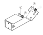
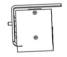
Breaking force monitoring on the floating carrier for mounting on igus® KMA connection elements or steel connection elements for e-chain systems® of the E4 and P4 series Connection - Via pigtail side 1 on sensor side 2 Harting HAN 3A - Four-wire, Harting HAN 3A M20 EMC industrial connector Pin assignment:
| Terminal | Designation | Color |
|---|---|---|
| X5/X6 – 4 | 24 V DC | brown |
| X5/X6 – 3 | GND | -- |
| X5/X6 – 2 | Input (4-20mA) | blue |
| X5/X6 – 1 | Shield | black |
Table 19: Connection of roller sensor to terminal X5 / X6
Mounting plate for cranes
Please provide the text you'd like me to translate.
Sensor orientation:
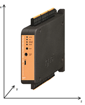
Built-in acceleration/orientation monitoring of the module, measurement is performed in all three spatial directions
Connection
- Already integrated in the module
Figure 14: Orientation of internal acceleration sensor
Commissioning and User Interface

Figure 16: Establishing a connection to the user interface
NOTE!
RNDIS driver may be required. Download the security keys here:
https://www.catalog.update.microsoft.com/Search.aspx?q=usb%5Cvid_0525%26pid_a4a2
Download the installation package here:
https://igus.widen.net/s/wlttsptqwb/sma_rdis-network-device-driver
USB
- Use a USB-A -> micro-USB cable.
- Plug the microUSB into i.Sense:modul II, USB-A into the PC.
- Access the user interface via IP address 10.0.0.1 in the browser address bar.
Figure 17: IP address (USB)
Driver Installation
- Download the security key here:
https://www.catalog.update.microsoft.com/Search.aspx?q=usb%5Cvid_0525%26pid_a4a2 - Open Device Manager
- Select Network Adapters / RNDIS device
- Click Update Driver
- Select the folder from the download
- Click "Install"
Alternatively:
1. Download the installation package here:
https://igus.widen.net/s/wlttsptqwb/sma_rdis-network-device-driver
2. Extract the compressed file
3. Run and install the installation package
WLAN (AdHoc)
- Activate the AdHoc network by pressing the "Reset" button on the front of the i.Sense:modul II for approximately 5 seconds.
- Within a few seconds, the WiFi network will appear with the SSID igus-isense.
NOTE!
AdHoc network credentials:
Wi‑Fi SSID: iSense-[nine-digit serial number]
Password: igusSmartPlastics!

Figure 18: AdHoc SSID
- Connect to the network igus-isense
- Access the user interface by entering the IP 10.0.0.1 or 192.168.128.1 in your browser address bar.
Sensor Commissioning
EC.P
- Place e-chain® in the middle of the travel path
- Set offset (user interface → Configuration, Sensor 1 and/or 2)
- Force limits are pre-configured by igus®
CF.P
- Place e-chain® in the middle of the travel path
- Set offset (user interface → Configuration, Sensor 1 and/or 2)
- Force limits are pre-configured by igus®
EC.B
- No calibration required
Operating the User Interface
- Three-bar menu in the upper left corner
NOTE!
Login credentials:
Username: igus
Password: igus_1432#
- Options: Sensors, Configuration, Alert Management, Wi‑Fi Setup
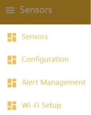
Figure 19: User interface menu
Configuration
NOTE!
To confirm changes: Code 1905
Sensors: - Select "Configuration" from the 3-bar menu in the upper left - Move the "configuration mode" slider to on (orange) - Enter data in the respective fields - Click the "Update Configuration" button
Zero Adjustment (Tare):
The tare function allows the force measurement to be referenced to the current state. When Tare is triggered, the currently applied measured value is adopted as the new reference point. Internally, the Force Offset is adjusted accordingly, so that the measurement from this point on is relative to this new reference value.
When to use:
- after installation or changes to the mounting situation
- when a constant residual value is displayed in the idle state
- before a measurement series, to relate the display to the current operating state
Note
Perform the zero adjustment only under stable conditions (no movement, no load changes) so that the reference value is set correctly.
CSV separator: - Default semicolon (;) - USA/Japan etc. comma (,)
When using multiple i.Sense:modul II devices: - Adjust USB IP address
If required, adjust the WiFi SSID device identification: - Default iSense-[nine-digit serial number]
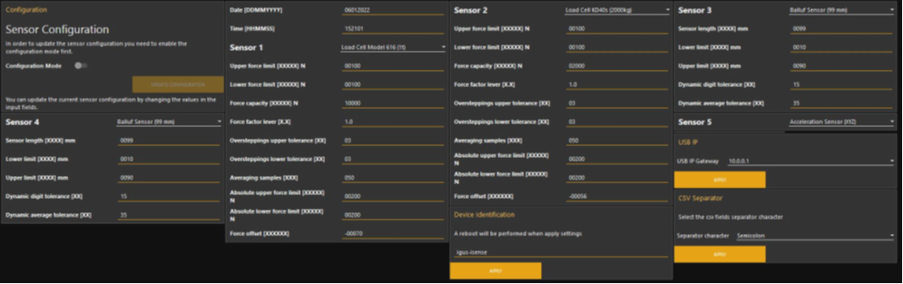
Figure 20: Sensor Configuration
Sensors
- Five columns (top to bottom): sensor status, graph (last minute), current values, configured limit values, "Reset Sensor" button
| Color | Meaning |
|---|---|
| GREEN | Everything in order / no action required |
| RED | Error / action required, click "Reset Sensor" to restart the measurement. If the error reappears, please contact customer service. |
| empty | Sensor connection is disabled |
Table 21: Sensor status indicators
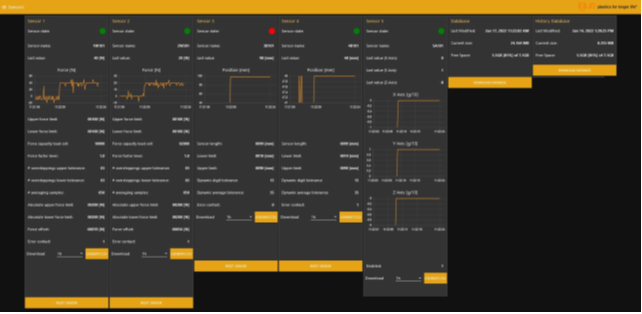
Figure 21: Sensor user interface
Sensor Reset
NOTE!
In the event of a sensor error, the error can be acknowledged and the measurement restarted by clicking "Reset Sensor".
Code: 1905
Alternatively: Press the "RESET" button on the front panel.
- Click the Reset button below the sensor
- A window for code entry will appear
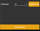
Figure 22: RESET SENSOR button
Data Download
- Measurement data can be downloaded as a CSV file for each sensor.
- Set the data volume in the field: 1h, 6h, 1d, 2d, 3d, 4d, 5d, 6d, 7d.
NOTE!
Data is stored in a ring buffer
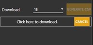
Figure 23: CSV data download
- Additionally, all available measurement data can be downloaded as an sqlite database:
- Database: all data over a period of at least 1 month
- Database History: Min./Max. values over a period (1h) over a longer time span
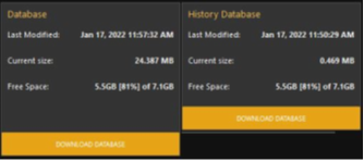
Figure 24: SQL database download
Alert Management
- Select "Alert Management" from the 3-bar menu in the upper left
- Select sensor
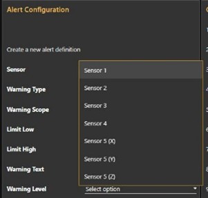
Figure 25: Sensor selection
- Assign alert type
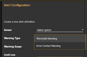
Figure 26: Alert type
- Enter data
NOTE!
Use a positive sign for Limit low and Limit high!
- Limit low: lower threshold value
- Limit high: upper threshold value
- Warning Text: text in SMS (max. 100 characters)

Figure 27: Threshold values and warning text
- Set warning level
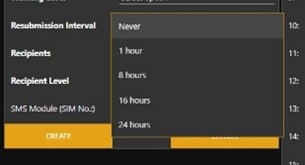
Figure 28: Warning level
- Set repeat interval
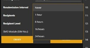
Figure 29: Repeat interval
- Enter phone number of SMS recipient

Figure 30: Phone number of SMS recipient
- Set permission level:
- 1 – may perform Reset
- 2 – read-only access
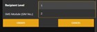
Figure 31: Permission level
- Clicking "Create" adds the alert message to the table on the right.
- The alert message can be deleted using the Delete button.
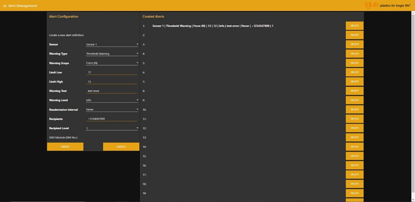
Figure 32: Message management
Wi‑Fi Setup
- Use the SCAN button to search for available Wi‑Fi networks.
- Select a network via "Select a Wi‑Fi".
- The SSID is displayed in the lower field.
- Enter the Wi‑Fi password in the "Password" field.
- Click "CONNECT" to connect the i.Sense:modul II to the selected Wi‑Fi network.
- The current network settings are displayed in the right window.
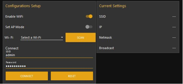
Figure 33: WiFi Setup
Please provide the text you'd like me to translate.
Performing Updates (Node-RED Frontend & Firmware)
Updates are part of product maintenance and should be applied regularly.
1) Update Node-RED Frontend (automatic)
The Node-RED frontend is updated automatically as soon as the module is connected to a Wi-Fi network.
Procedure for pending updates: 1. Connect the module to a Wi-Fi network. 2. Wait until the automatic Node-RED update is complete. 3. The update is complete when the module restarts automatically.
Note for older software versions (different update behavior)
With older software versions, the Node-RED frontend update may be started automatically in the background, without this being clearly indicated in the user interface.
In this case, the i.Sense dashboard may be temporarily unreachable or appear to "freeze".
Simply wait a few minutes (typically 2–5 minutes) until the dashboard appears normal again.
Do not interrupt the device during this time (do not switch it off, do not disconnect).
2) Performing a Firmware Update (manual)
Firmware updates must be applied manually.
Procedure for pending updates
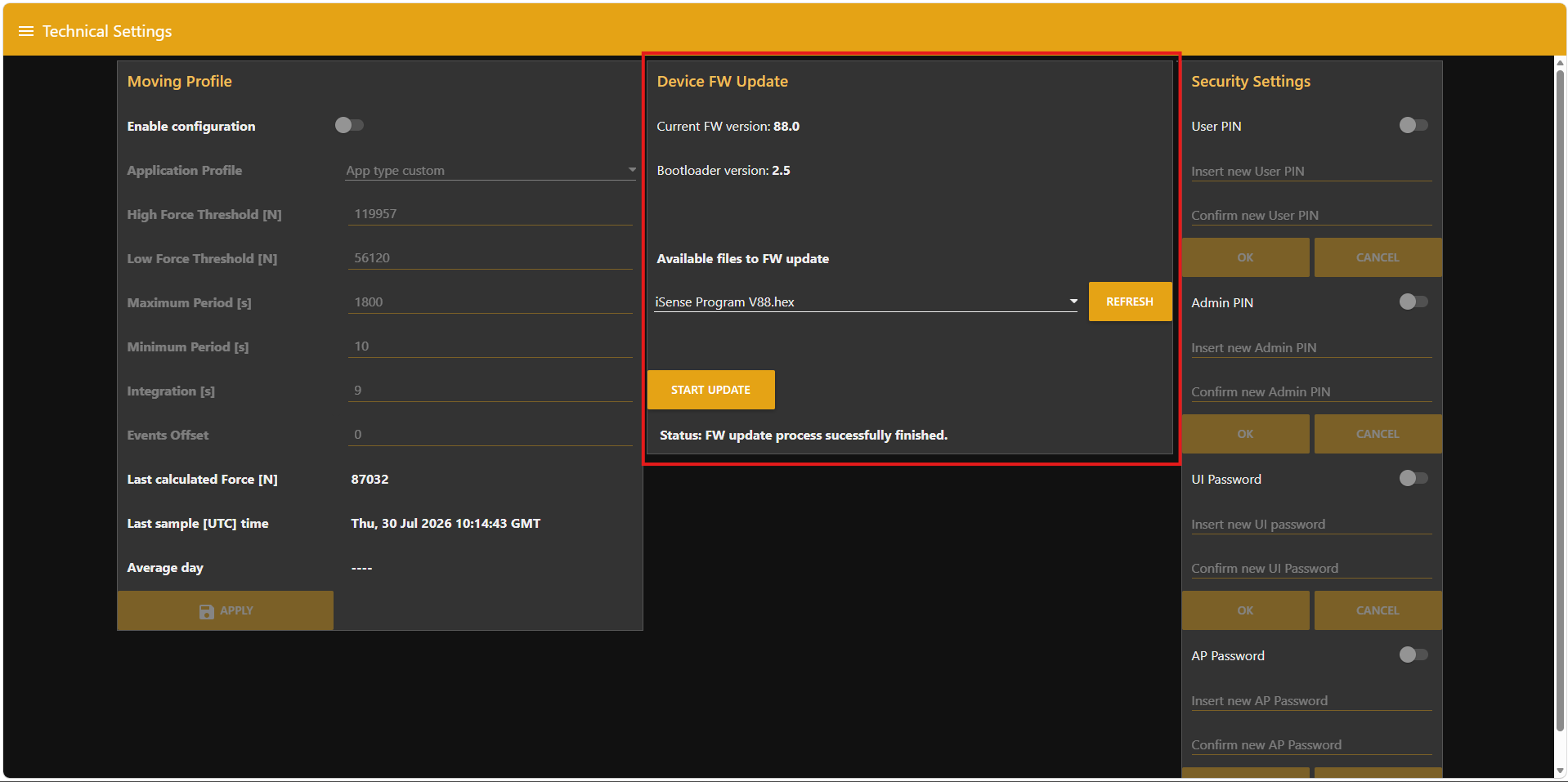
- Open the Technical Settings menu item in the user interface.
- Enter the password you have chosen or the default password 1905.
- Select the latest firmware package.
- Start the installation and wait until the process is fully complete.
- Afterwards, check the firmware version and the correct functioning of the system.
CAUTION!
Do not interrupt a firmware update in progress (e.g. by cutting the power supply or disconnecting). An interruption can lead to malfunctions.
LED behavior during firmware update & restart
- During a firmware update, the status LEDs may flash rapidly (update/write process).
- During the subsequent restart, the LEDs may briefly go out and then light up again.
This behavior is normal.
Please provide the text you'd like me to translate. The identifier at the beginning of each sensor message is structured according to the following format.
XXXXX;
| X | XX | XX |
|---|---|---|
| 1 = Sensor 1 (2mV/V) 2 = Sensor 2 (2mV/V) |
W1 = Vishay load cell model 616 (1t) W2 = Vishay load cell model 620 (2t) W3 = ME Messsysteme load cell KD40s (2000kg) D1 = strain gauge force sensor (small form factor) D2 = strain gauge force sensor (large form factor) 00 \= deactivated |
01 = Version 00 = deactivated |
| 3 = Sensor 3 (4-20mA) 4 = Sensor 4 (4-20mA) |
B1 = Balluf sensor (99mm) B2 = Micro-Epsilon (300mm) B3 = WayCon (1000mm) 00 \= deactivated |
|
| 5 = Sensor 5 (XYZ) | A1 = Acceleration (XYZ) 00 \= deactivated |
Table 22: Sensor identifier structure
Please provide the text you'd like me to translate.
Load Cells and Strain Gauge Sensors
| Bezeichnung | Format |
|---|---|
| Sensor Identifier | XXXXX; |
| Date | DD.MM.YYYY; |
| Time | HH:MM:SS; |
| Absolute Upper Force Limit [N] | XXXXXX; |
| Upper Force limit with allowed numbers of force tolerance oversteppings [N] | XXXXXX; |
| Actual Force [N] | XXXXXX; |
| Lower Force Limit with allowed number of force tolerance oversteppings [N] | XXXXXX; |
| Absolute Lower Force Limit [N] | XXXXXX; |
| Number of upper force tolerance oversteppings [n] | XX; |
| Number of lower force tolerance oversteppings [n] | XX; |
| Number of force samples until averaging [n] | XXX; |
| Force offset [N] | XXXXXX; |
| Position [mm] | XXXXXX; |
| Status Potential-free contact (1=closed, 0=open) | X;\r\n |
Table 23: Structure of output string for load cells and strain gauge sensors
Breaking Force Sensor
| Bezeichnung | Format |
|---|---|
| Sensor Identifier | XXXXX; |
| Date | DD.MM.YYYY; |
| Time | HH:MM:SS; |
| Lower Position Limit [mm] | XXXX; |
| Actual Position [mm] | XXXX; |
| Upper Position Limit [mm] | XXXX; |
| Sensor length [mm] | XXXX; |
| Dynamic digit tolerance [n] | XX; |
| Dynamic average tolerance [n] | XX; |
| Status Potential-free contact (1=closed, 0=open) | X;\r\n |
Table 24: Structure of output string for breaking force sensor
Acceleration Sensor
| Bezeichnung | Format |
|---|---|
| Sensor Identifier | XXXXX; |
| Date | DD.MM.YYYY; |
| Time | HH:MM:SS; |
| Acceleration x-Axis [g/10] | XX; |
| Acceleration y-Axis [g/10] | XX; |
| Acceleration z-Axis [g/10] | XX;\r\n |
Table 25: Structure of output string for acceleration sensor
Example Strings
1W101;24.03.2021;12:34:01;+07000;+05000;-01453;-05000;-07000;05;05;050;-00980;;1;\r\n 2D101;24.03.2021;12:34:01;+05000;+03000;-00453;-03000;-05000;01;01;100;-00580;;1;\r\n 3B101;24.03.2021;12:34:01;0010;0050;0090;0099;15;35;1;\r\n 4B101;24.03.2021;12:34:01;0010;0045;0090;0099;15;35;1;\r\n 5A101;24.03.2021;12:34:01;+01;-02;+02;\r\n
Please provide the text you'd like me to translate.
Warnings (Alerts)
| LED (lit) |
Description | State of potential-free contacts |
|---|---|---|
| Green (Active) | LED is on as soon as a measurement is active. No action required, everything is fine. | high |
| Green (run) | LED is on as soon as the device is ready for access via IP address to the GUI. | high |
| Yellow (replace battery) | LED is on as soon as the buffer battery for the RTC is empty. Replace the battery. A description can be found on page 7 under 1.5 Maintenance/Battery Replacement. Caution: Switch off the device before any intervention and ensure it is de-energized. Otherwise there is a risk of physical injury and malfunctions. Only use batteries with exactly the same specifications: Lithium button cell type CR 1225 3V 50mAh. Note: To replace the battery, the housing must be opened. To maintain warranty claims, you must discuss this with the responsible igus® branch beforehand. Any other approach will void the warranty claim. Note: After replacing the battery, the date and time as well as all parameters in the setup area must be reconfigured. |
high |
| none | The device is disconnected from the power supply | low |
Table 28: Warnings, errors and potential-free contact
Errors
| LED (flashing) | Description | State of potential-free contact |
|---|---|---|
| Red (Error) once | Fault sensor 1 | low |
| Red (Error) twice | Fault sensor 2 | low |
| Red (Error) three times | Fault sensor 3 | low |
| Red (Error) four times | Fault sensor 4 | low |
Table 29: Definition red flashing
| LED (lit) | Description | State of potential-free contacts |
|---|---|---|
| Red (Error) | Multiple sensors are in a fault state | low |
Table 30: Definition red lit
NOTE!
Check the error status using the potential-free contacts or take a look at the user interface. Clicking Reset acknowledges the fault and restarts the measurement.
Maintenance
CAUTION!
Do not open the device in wet conditions or with wet hands. Always ensure the correct polarity of the battery (see red marking in Figure 1 on the right). Otherwise, there is a risk of fire and explosion. Replace the battery only and exclusively with a type with the exact same specifications (battery type: CR1225/3V).
NOTE!
The i.Sense:modul II may only be serviced by qualified specialist personnel. Please refer to Chapter 1.2 (Qualified Personnel) for this purpose. Should hardware problems occur that are attributable to non-qualified personnel, the warranty will be void. If other hardware problems occur, please contact our customer service (see page 30). Spent batteries must not be disposed of in household waste. The batteries must be handed in at a collection point for used batteries.
Inside the i.Sense:modul II, on the circuit board, there is a battery of type CR1225 3V (see red marking in Figure 1 on the right). During the period in which the 24V supply voltage is switched off, the battery ensures that the date and time are retained. The battery must be replaced as soon as the status LED labelled "Replace Battery" lights up yellow (see red marking in Figure 1 on the left).
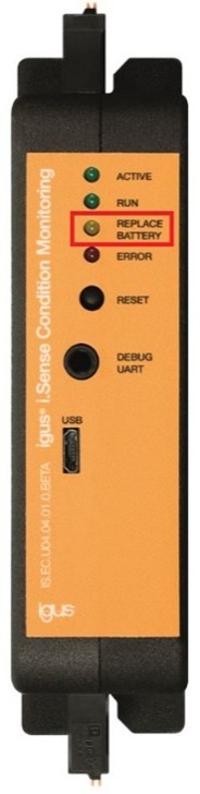
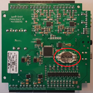
Figure 1: IS.EC.U04.04.01.0 - Battery
When replacing the battery, completely disconnect the device from the power supply. Disconnect all connected terminals from the device and remove the device from the DIN rail. Remove the front sticker and unscrew the 4 screws on the right unlabelled half of the housing.
(Should the sticker be damaged during opening, please contact igus® customer service to order a replacement). The left and right sides of the housing can then be carefully pulled apart at the front and back using the thumbs, from top to bottom.
NOTE!
After a battery replacement, the date/time parameters will be lost. To apply a new date/time, all parameters must be re-entered in the graphical user interface in configuration mode. Please proceed as described in Chapter 7.3 "Operating the User Interface" on page 19.
Troubleshooting
- No connection to the device possible.
- Check whether network adapter / RNDIS driver is installed
- If necessary, reinstall the driver (p. 19)
- Loss of connection or problems with the user interface:
- Reload the page
- In the menu, click again on the desired view
- If this fails, restart the device and try again.
- If this attempt also fails, please contact customer service (p. 31).
- The device is not retrieving all sensor data, what now?
- Check all connectors and restart the system.
- Otherwise, contact customer service (p. 31)
FAQS
- How are the sensor limits set?
- User interface -> Configuration mode
- How do you retrieve the determined sensor data?
- Under the User interface section, the individual steps for operating the user interface are listed.
- Is it possible to download the data from the user interface?
- Under the User interface section, one option for downloading the sensor data is mentioned.
Abbreviation
| Abbreviation | Description |
|---|---|
| EMC | Electromagnetic Compatibility |
| ESD | Electrostatic Discharge |
| GUI | Graphical User Interface |
| PLC | Programmable Logic Controller |
| Table 32: Abbreviations |
Definition of Terms
| Abbreviation | Description |
|---|---|
| Force Factor | Factor by which the measured force is multiplied (lever arm) |
| Microsoft Excel | Spreadsheet application by Microsoft |
| Outer Force Limit | A single exceedance of this limit value triggers the sensor |
| Inner Force Limit | Multiple exceedances of this limit value within a certain period of time trigger the sensor (the specifications for this are defined in the input fields) |
| Table 33: Glossary |
Please provide the text you'd like me to translate.
Circuit Diagrams
Attached after page 31.
Regulatory & Legal
Compliance with EU Directives The CE marking on the i.Sense confirms conformity with the following European directives:
| Directive | Description |
|---|---|
| 2014/30/EU Electromagnetic Compatibility (EMC) | Directive of the European Parliament and of the Council on the harmonisation of the laws of the Member States relating to electromagnetic compatibility |
| 2014/53/EU | Directive of the European Parliament and of the Council on the harmonisation of the laws of the Member States relating to the making available on the market of radio equipment and repealing Directive 1999/5/EC |
| 2011/65/EU RoHS | Directive of the European Parliament and of the Council on the restriction of the use of certain hazardous substances in electrical and electronic equipment |
The applicable directives are listed in the EU Declaration of Conformity for the respective device.
Please provide the text you'd like me to translate.
Note on the Cyber Resilience Act (CRA) The i.Sense contains digital components. Such products are subject to the security requirements of the EU Cyber Resilience Act (Regulation (EU) 2024/2847). The CRA stipulates that software and networked devices must be operated securely and kept up to date throughout their entire lifecycle.
To ensure that you can use the i.Sense reliably and securely, please observe the following: - Install provided firmware and software updates on a regular basis. - Use secure network and access settings. - Change default passwords immediately after commissioning. - Disable interfaces or services that are not required.
If you notice a technical anomaly or a potential security vulnerability, please report it via the official igus support channel or through the service portal. The CRA also requires that users have access to information about security support, known risks, and update processes. Further details can be found in the documentation for this product or from your national market surveillance authority.
Please provide the text you'd like me to translate.
Note on EU Dual-Use Regulation (EU) 2021/821 Individual electronic components and sensors in the i.Sense may, depending on their technical configuration, be subject to the EU Dual-Use Regulation (EU) 2021/821. This regulation governs goods that can be used in both civilian and military applications.
An export licence may therefore be required for export to countries outside the EU. Whether this applies depends on the destination market, the intended use, and the specific technical configuration.
Please verify the following before transferring or exporting the product: - whether export restrictions apply to your destination country, - whether your application is considered security-critical or military in nature, - whether authorisation is required under applicable regulations.
Further information is available from your national export control authority (e.g. BAFA in Germany) or in the official EU documentation.
Service
Customer Service
de-smartplastics-service@igus.net
+49 (0) 2203 9649 9806
Technical support for igus® smart plastics
Documentation/FW
https://www.igus.de/info/i-sense-modul-2
Download of manuals, FW updates and certificates
Website smart Plastics
https://www.igus.de/info/vorausschauende-wartung-smart-plastics
Option to order sensors, processing units and further accessories
Contact
+49 2203 9649-9507
Imprint
© 2026
All rights reserved by
igus® SE & Co. KG
Spicher Str. 1a
51147 Cologne